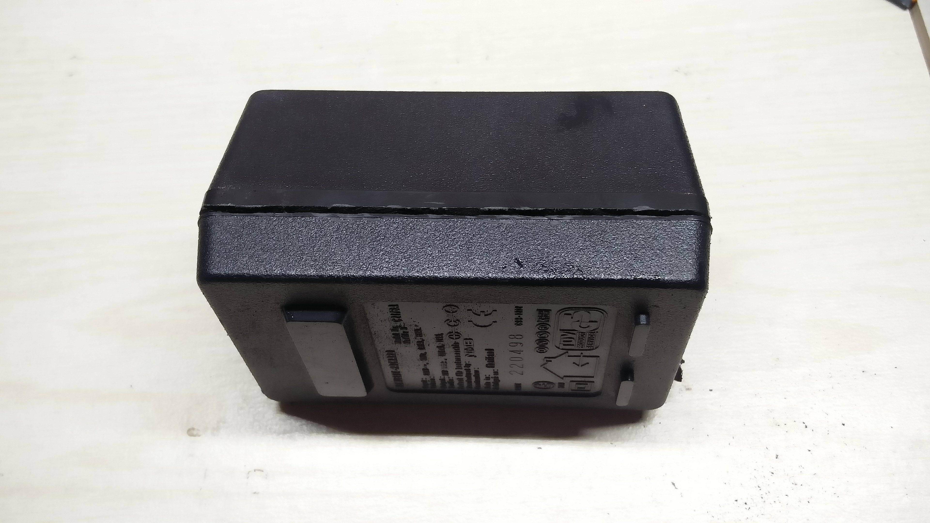
Recently I've found an PSU from old HP Inkjet printer. It is very heavy, suggesting that the supply is not a switched-mode one, but a linear one, involving a transformer as main voltage conversion element.
What is an transformer?
Transformer is an inductor, which role is to transform one voltage to another. We can either step up or step down or even keep voltage at the same level. There are four types of transformers:
- Step-up transformer
- Step-down transformer
- Isolation transformers
- Autotransformer
Transformer has two sides: primary and secondary. To primary winding you connect our input voltage and from secondary winding we are getting our output voltage depending on turn ratio between primary and secondary. Transformer is basically two coils wound around an ferro-magnetic core. Turn ratio is 7:1 then output voltage is seven times smaller than the input voltage, like case of this power brick.

Teardown
Whole construction was like a brick. Rigid, solid and enough to kill someone when thrown. Weight itself was big enough hint that PSU has a transformer inside. To open it up, I had to use a Dremel with a cutting wheel with some skrewdriwer brute-force - the chassis is glued togheter.

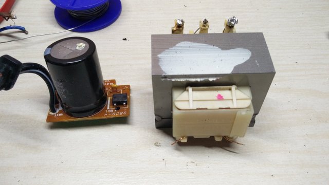
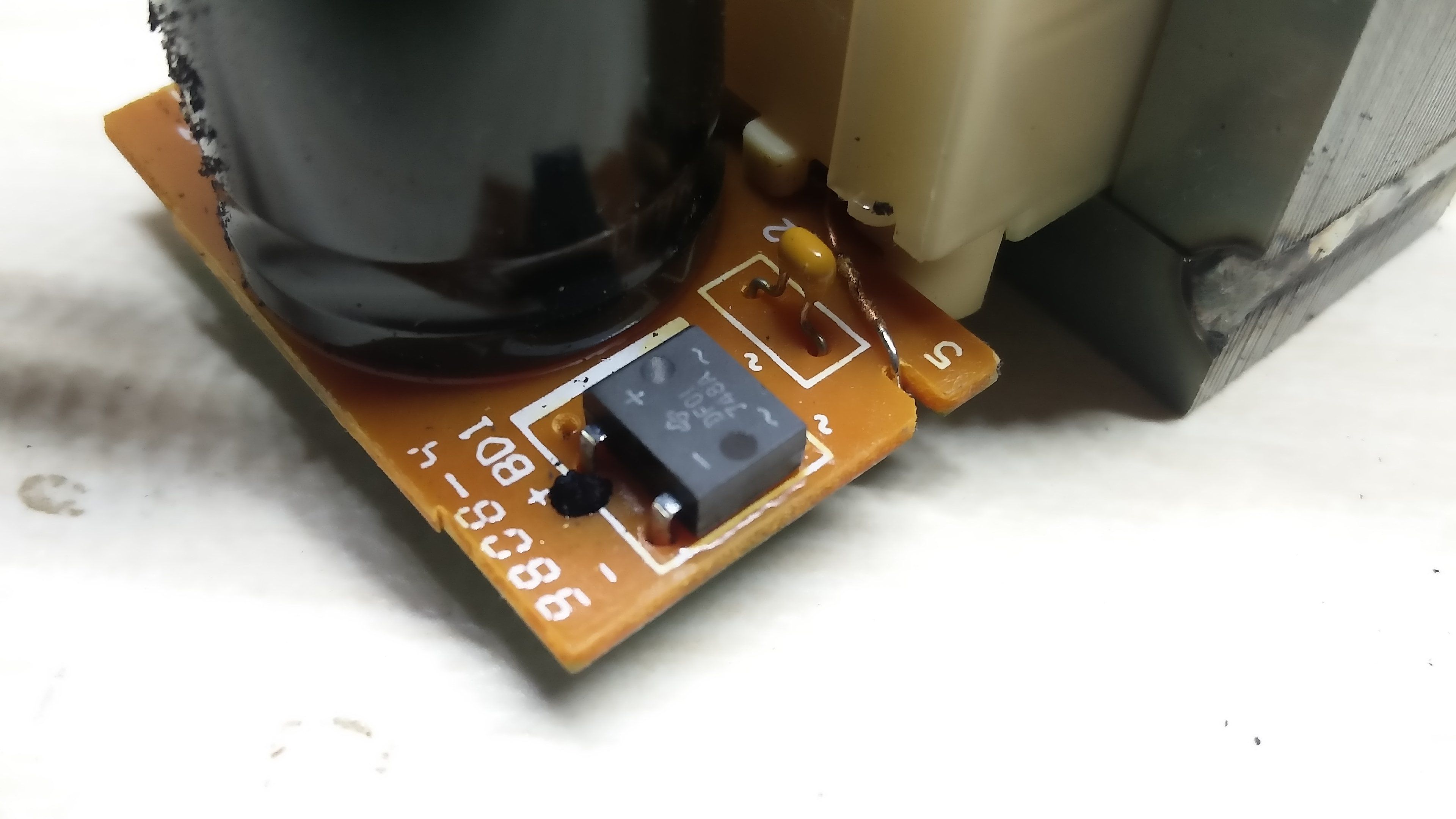
Inside is bare-bone. Not even single voltage regulator, probably the regulator will be inside of the device powered by this brick. We have there our transformer, an integrated bridge rectifier, which converts AC to bumpy DC and two capacitors, to smooth and filter out noise coming from mains.


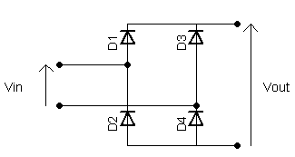
Full-bridge rectifier consists of 4 diodes in arragement like this:

Working principal is simple. AC present in power outlets is changing it's direction at 60Hz (about every 0,017s). Diodes connected like this are forcing current to flow only one way, no matter the direction. It's not blocking reverse current like single diode would do it - it actually forces to flow in one direction.
Direction of first AC cycle goes like this:

...and the second AC cycle:

Voltage on the output will be equal (minus forward voltages of the diodes) to peak voltage of the transformer (after smoothing it out with a capacitor).
Remarks
This power brick takes 230V as input voltage and outputs about 400mA@30V, transformer's turn ratio is about 7:1.
Due to big voltage at output, transformer can be used as base for a variable bench power supply, because I can easily achieve any voltage between 0-30V. I think that it might be my next project.
Cheers!
The post has been very informative.
Downvoting a post can decrease pending rewards and make it less visible. Common reasons:
Submit
Thank you :)
Downvoting a post can decrease pending rewards and make it less visible. Common reasons:
Submit