**Originaly posted by me on Wordpress:
Formula 1 power unit is a masterpiece of modern technology. A currently used (from 2014 season) formula one power unit comprises of an ICE (Internal Combustion Engine) and MGUs (Motor Generator Units). An ICE used in F1 is a 4 stroke (Intake, Compression, Power and Exhaust) cycle gasoline (petrol) engine and works on same principle as that of the normal car engine. MGU in F1 are two energy recovery systems which recovers energy from braking (i.e. MGU-K) and exhaust gases (i.e. MGU-H). Energy recovered from these systems is stored in a storage system and used when needed for boost.
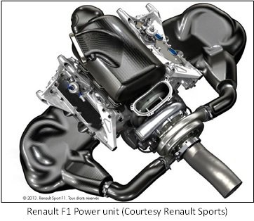
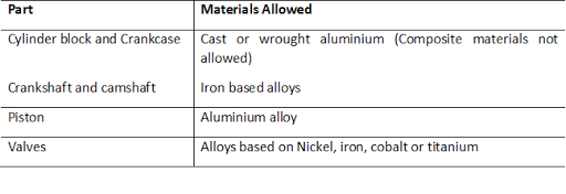
F1 ICE works on same principle as that of normal car engine but is very compact and very powerful compared to normal car engine. It is 1.6 liters in volume and produces 600 Hp (448 kW) compare to normal car which can produce 110 Hp (82kW) to 120 Hp (89.5 kW) in same volume. It has 6 cylinders arranged at 90˚ in V. The engine has very high revolution output up to 15000 rpm (revolutions per minute). The Bore (cylinder diameter) of the engine is 75 to 80 mm and stroke (piston travel from top of the cylinder to its bottom) is 48 to 53 mm. Therefore, the bore to stroke ratio is in range of 1.4 to 1.5 which is greater than normal car engine which has bore to stroke ratio lesser than 1. F1 engine uses a compression ratio of 12:1 (i.e. air taken in at intake stroke is compressed to 12 times smaller volume during compression stroke). Materials used for different parts of ICE are regulated by FIA (Federation Internationale De L’Automobile).
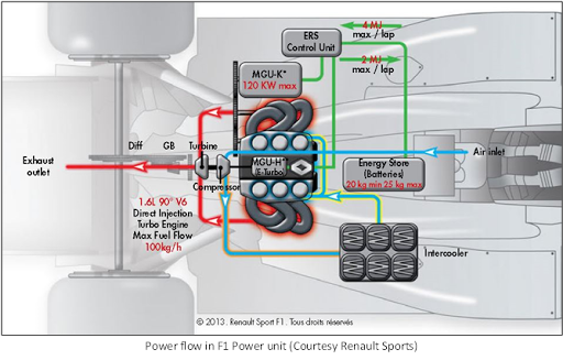
F1 ICE uses a turbocharger to pressurise the intake air for the engine. F1 turbocharger uses single stage turbine and compressor mounted on same shaft which revolves at speed above 120000 rpm. This system makes it possible to recover large amount of heat energy that would be wasted. Also the intake of a F1 ICE is faced to the direction of wind flowing over vehicle as it moves forward. This causes to forced induction of air as kinetic energy of air is converted in to pressure energy. Therefore the forced induction and turbocharging increases density of air inside intake manifold (pipe) by double compare to atmosphere.
Brake mean effective pressure in an F1 ICE is 28 to 32 bars. To prevent detonation and preignition F1 engine uses very high quality fuel with octane number of 93 to 96. Also, unlike normal engines F1 engine doesn’t use manifold or port injection but uses direct injection which injects gasoline inside cylinder at 500 bars which prevents preignition as there is no fuel before timed ignition. High bore to stroke ratio (over square configuration) also reduces flame propagation time as distance to be travelled by flame is reduced producing quicker combustion and therefore, results high peak pressure and very low chances of detonation.
Friction in an engine increases with increase in speed of the engine. Main factor contributing friction is viscous friction between piston and cylinder wall. This frictional force is product of shear stress and surface area of contact. The shear stress increases with increase in velocity gradient (i.e. differences of velocities of surfaces in contact.)
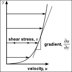
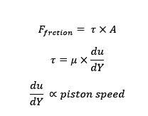
Therefore if piston speed increases viscous friction will increase and at speed of 13000 rpm piston speed is very high. To avoid this F1 ICE uses 6 cylinders instead of using 3 or 4 cylinders like in a normal engine. This reduces displacement per cylinder and therefore, piston travel per revolution resulting low piston speed. Also high bore to stroke ratio reduces vertical piston travel and therefore piston speed. Frictional force also depends upon coefficient of viscosity therefore F1 uses advanced synthetic lubricants which have low coefficient of viscosity. To reduce height of centre of gravity and to avoid problem of oil spilling during high accelerations F1 engine uses a dry sump lubrication system. In this System lubricating oil is placed in a tank somewhere far than engine instead of placing it in crank case. This makes it a compact system.
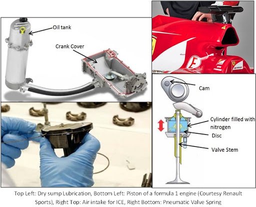
F1 engine needs to be structurally really strong as failure may cause huge loss during the race. Stresses due to inertia are very high in F1 engine due to high operating speed. At some times piston experiences accelerations up to 8000 times of gravity (as it accelerates from 0 to 100km/h in less than 1/2000th of a second). Generally, weight of the piston lies between 200 to 250 grams but when the engine runs at speed rpm of 15000 i.e. 250 revolutions per second connecting rod experiences force up to 1.5 tons. Inertial stresses in F1 engine are minimised by some level by lowering reciprocating speed using high bore to stroke ratio and more numbers of cylinders. Formula 1 engines are designed for very low life of 2500 to 3000 kms compare to normal car engines which are designed for life of 1,000,000 kms of life. Therefore the dimensions are very less. For example, figure shows piston in earlier V8. It has very short piston skirt and very low crown thickness.
At very high speed (rpm) valve springs slows down due to inertia and to avoid this valve spring needs to be stiffer therefore more force and hence more power will be required for opening the valves. To tackle this problem F1 ICE uses pneumatic valve springs. This consists of disc acting as a piston attached to the valve stem and surrounded by a cylinder. The cylinder is filled with nitrogen gas. When valves are actuated piston compresses the gas and decompresses when relived.
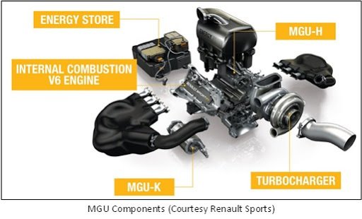
Performance variation in MGUs of a F1 car can be difference between victory and failure. MGUs in F1 have function to recover energy, store energy and provide boost when needed. Current F1 cars use two types of MGUs. These are MGU-K (K for kinetic) and MGU-H (H for heat). Turbocharger shaft is connected to MGU-H which converts some part of energy from turbocharger into electricity and stores it to storage system. During a turn driver brakes the car which causes the engine speed to reduce and therefore, reduces the speed of the turbocharger’s turbine. As the car leaves the corner driver pushes the throttle really hard however, turbine speed takes some time to recover (note that working speed of turbine is above 100000 rpm). This time is called as turbo lag. Turbo lag causes reduction in engine acceleration and therefore, car’s acceleration. Therefore, the MGU-H acts as motor and supplies boost power to turbine to recover its speed quickly. MGU-K in F1 is used to recover energy during braking of the car. The operating speed of the MGU-K is 50000 rpm and capable of recovering 161 Hp (120 kW). MGU-K transfers energy to storage system (batteries or ultra-capacitors). This energy is used automatically when high acceleration is needed or can be used by driver manually for overtaking overriding the electronic programme.
#FormulaOne #PowerUnit #Racing #Engineering #Engine #Hybrid
Hi! I am a robot. I just upvoted you! I found similar content that readers might be interested in:
https://kbad1000.wordpress.com/2015/12/
Downvoting a post can decrease pending rewards and make it less visible. Common reasons:
Submit
that is my own blog, I myself have added the link to it in my post. I've to flag you for robotic behaviour.
Downvoting a post can decrease pending rewards and make it less visible. Common reasons:
Submit
https://kbad1000.wordpress.com/2015/12/
that is my own blog, I myself have added the link to it in my post at the top. I'd to flag @cheetah for robotic behaviour (which is obvious)
Downvoting a post can decrease pending rewards and make it less visible. Common reasons:
Submit