Description:
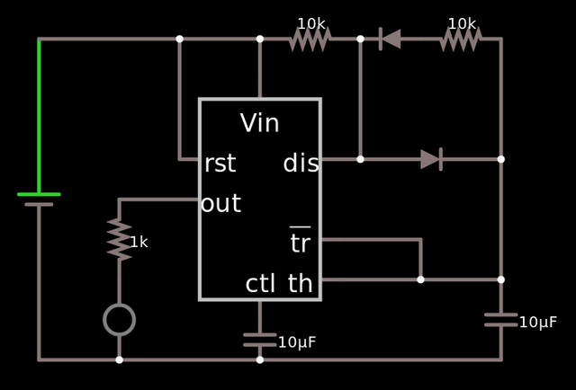
- Generate square wave output using IC555
- Pulse width modulation with diodes
- Adjust frequency with resistors
Components:
- NE555P x 1
- 10kOhm resistor x 2
- 1N4007 diodes x 2
- 10uF capacitors x 2
- Red LED x 1
- Jumper wires
(Optional – to compare LEDs) - 1kOhm resistor x 1
- Red LED x 1
Schematic:

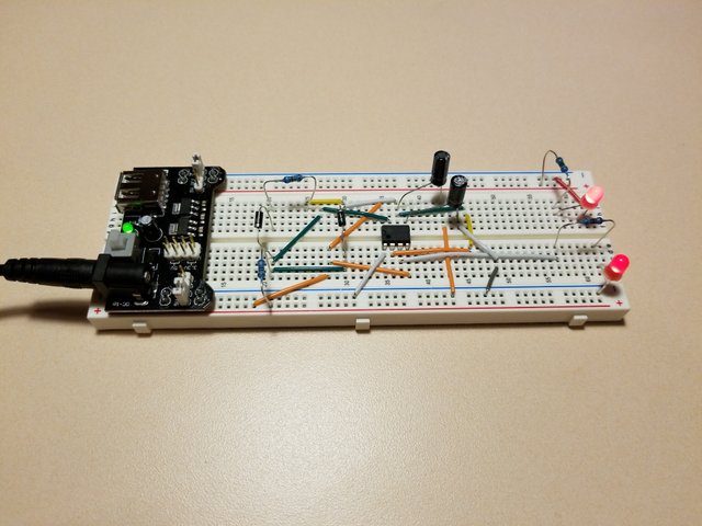
Breadboard:

Data:
- LED frequency: 6.07Hz
- Duty cycle: 50/50
Resources:
IC 555 Timer Working: Pin Diagram & Specifications
https://electronicsforu.com/resources/learn-electronics/555-timer-working-specifications
How a 555 Timer Works
How to Control the Duty Cycle of a 555 Timer
Schematic Simulation
http://falstad.com/circuit/circuitjs.html
✅ @sodnupta, I gave you an upvote on your first post! Please give me a follow and I will give you a follow in return!
Please also take a moment to read this post regarding bad behavior on Steemit.
Downvoting a post can decrease pending rewards and make it less visible. Common reasons:
Submit
Congratulations @sodnupta! You have completed some achievement on Steemit and have been rewarded with new badge(s) :
Click on the badge to view your Board of Honor.
If you no longer want to receive notifications, reply to this comment with the word
STOPDownvoting a post can decrease pending rewards and make it less visible. Common reasons:
Submit