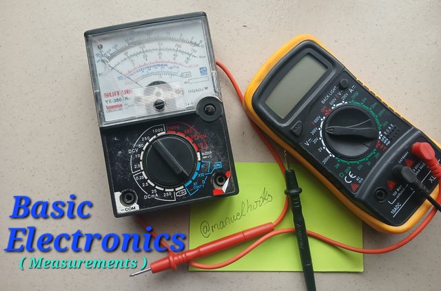
 Captured by @manuelhooks
Measurement and Measuring Instruments
In Electronics we work with a lot of quantities like voltage, current, resistance, capacitance, inductance and a lot more. These quantities are not visible to the naked eyes but has to be balanced in the proper ratio for a device to work successfully.
To measure these quantities, we make use of different meters as shown in the table below.
| Quantity | Measuring instrument |
|---|---|
| Voltage | Voltmeters |
| Current | Ammeter |
| Resistance | Ohmmeter |
| Frequency | Oscilloscope |
| Inductance | LCR meter |
| Capacitance | Capacitance meter |
| Multiple Quantities | Multimeter |
Having stated that diffrent devices are used to measure different electrical and electronic quantities, for the sake of convinence a multimeter is a single device with adjustable functions such that diffrent quantities can be tested with it.
In this workshop, I wiill be using a SUNWA YX-360TRes Analogue Multimeter.
SUNWA YX-360TRes can measure the following quantities.
| Quantity | Range |
|---|---|
| DC Voltage | 2.5mv, 10v, 50v, 250v, 1000v |
| DC mA | 0.25, 2.5mA, 25mA, 250mA |
| AC Voltage | 10v, 50v, 250v, 1000v |
| Resistance | x1, x10, k |
| Battery | 1.5v |
| Continuity | |
| Diode | |
| hFE |
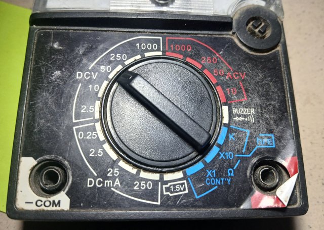 function selector nub

Workshop 1
Component measuring/testing instruments:
Example 01:
Measurement of Voltage(V)
Step 1 [Identify the quantity]
The quantity is AC Voltage
Turn the function selector knob to ACV
Step 2 [Connect test probs]
Connect the black prob to -COM and the red prob to +
Step 3 [Identify the range to be used]
The Power grid in Nigeria supplies 240v
Set range to 250v of AC
Step 4 [Test Expectation]
If all is well, the needle should travel down to this position on the scale.
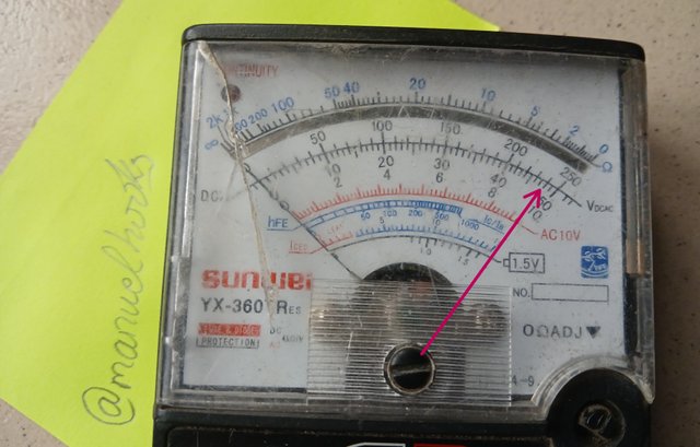
If the needle fails to move at all, there is no power.
Step 5 [Connect probes]
Insert the multimeter's probes into the power outlet holes on the wall to get the reading. There is no polarity so you can interchange the position.
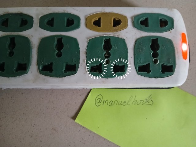
Step 6 [Observation]
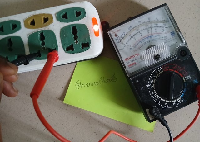
The voltage supplied is 175v of alternating current insted of 240v.
Example 02:
Measurement of Resistance
Step 1 [Identify the quantity]
The quantity to be mesured is Resistance.
Turn the function selector knob to Ohmmeter Ω
Step 2 [Connect test probes]
Connect the black probe to -COM and the red prob to +
Step 3 [Identify the range to be used]
The surface mounted resistor is labeled as 202. This makes it a resistor of 2000Ω
Step 4 [Test Expectation]
If all is well, the needle should travel all the way to 2 on the graduated scale.
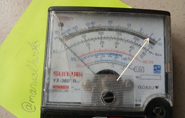
Step 5 [Connect probes]
Touch the two ends of the resistor with the test probe as shown in the pictures below
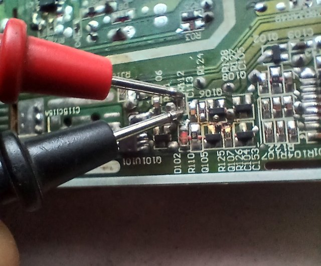
To make sure I don't get a wrong reading I had to cut one of the connection to the resistor to isolate it from the circuit.
Step 6 [Observation]
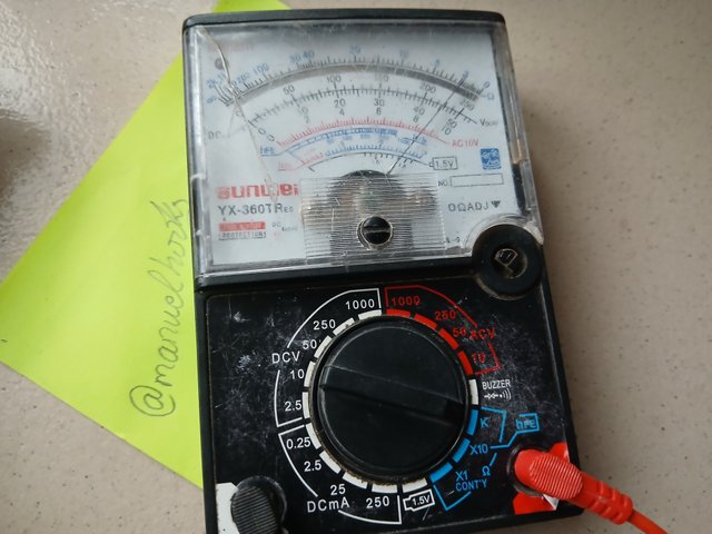
As expected, when the function was set to KΩ the needle moved all the way to point 2 indicating 2kΩ.
Example 03:
Measurement of DCV
Step 1 [Identify the quantity]
The quantity is Direct Current Voltage (DCV)
Turn the function selector knob to DCV
Step 2 [Connect test probes]
Connect the black probe to -COM and the red prob to +
Step 3 [Identify the range to be used]
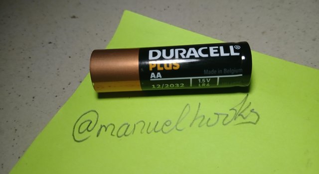
I will be testing a DURACELL AA battery and I am expecting 1.5v of DC as it is clearly written on the battery
Set range to 10v DC
You can also use the 1.5v test function
Step 4 [Test Expectation]
If all is well, the needle should travel down to this position on the scale.
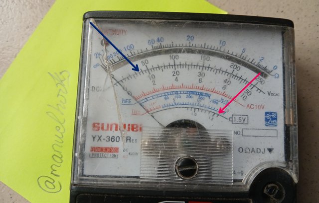
If the function knob is on the 1.5 v function for battery, the needle should be positioned as indicated by the red arrow.
If the function is set to 10v DC then the needle should stop as indicated by the blue arrow.
Step 5 [Connect probes]
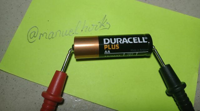
The red prob goes to the positive terminal of the battery and the black goes to the negative terminal as shown in the picture.
Step 6 [Observation]
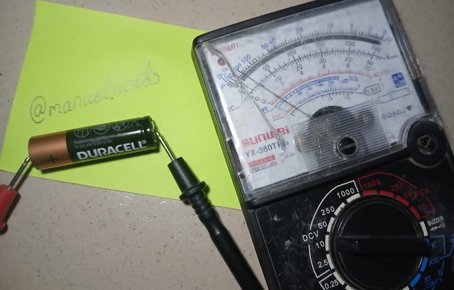
When function was set to 10v of DC, the battery was supplying 1v a little short of the expectation.
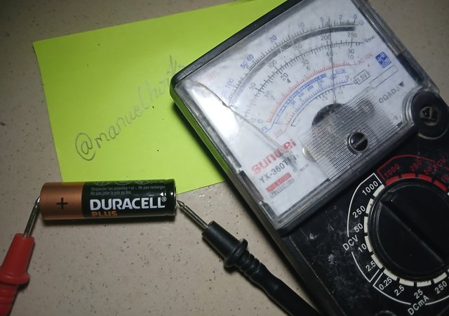
When the function was set to 1.5 v battery tester the reading was about 1.25 a little less that expected.
Example 04:
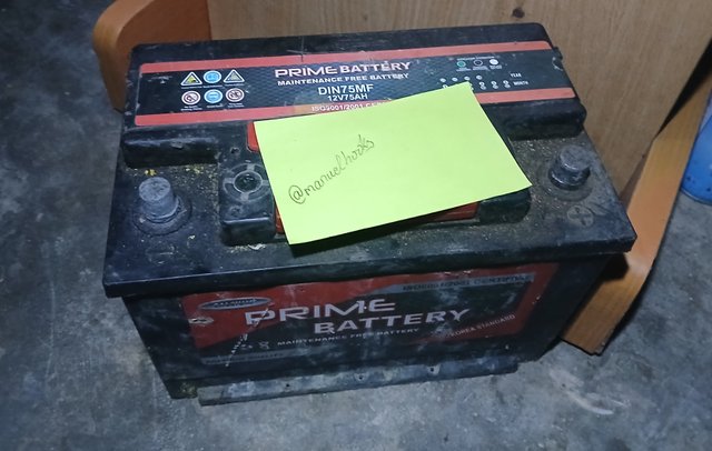
Measurement of DCV on car battery
Step 1 [Identify the quantity]
The quantity this time is still DCV
Turn the function selector knob to DCV
Step 2 [Connect test probes]
Connect the black probe to -COM and the red prob to +
Step 3 [Identify the range to be used]
It is clearly printed on the battery 12v 75AH
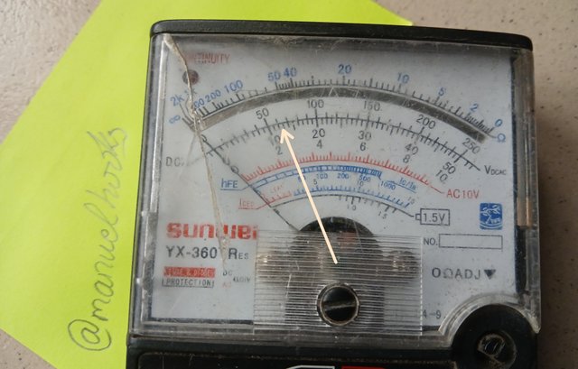
Set rang to 50v
Step 4 [Test Expectation]
If all is well the needle should be positioned at point representing 12 based on the selected range as shown below.
Step 5 [Connect probs]
Touch the negative terminal of the battery with the black prob and the positive terminal with the red probe.
Step 6 [Observation]
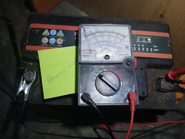
Insted of 12v this battery is peoducing 9v of direct current.
Example 05:
Testing a Diode
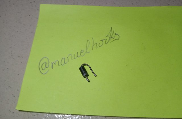
Step 1 [Identify the quantity]
The diode testing
Turn the function selector knob to BUZZER
Step 2 [Connect test probes]
Connect the black probe to -COM and the red prob to +
Step 3 [Identify the range to be used]
There is no range for this function
Step 4 [Test Expectation]
If all is well the diode is forward biased, the buzzer will make a sound but when the probes are reversed, we get no sound at all.
Step 5 [Connect probes]
The red prob connects to the side of the diode that has a colour strip, the black connects to the other end of the diode. This is forward biased.
After this, you may reverse the connection to get a reversed biase.
Step 6 [Observation]
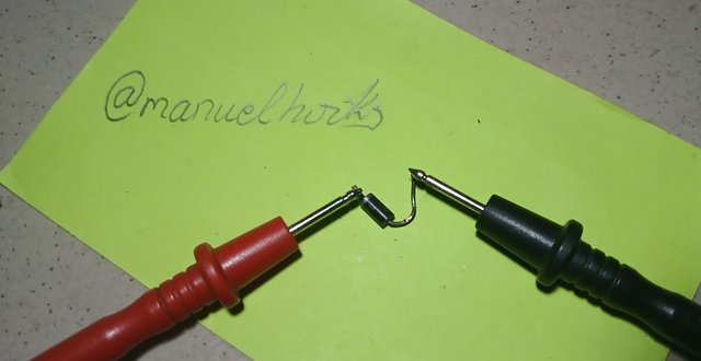
When the diode is forward biased, the buzzer makes a sound
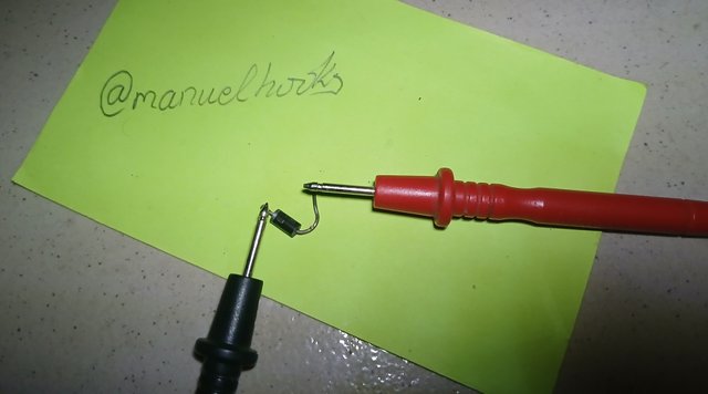
When the connection is reversed biased, the buzzer will not make any sound.
Example 06:
Testing a Fuse
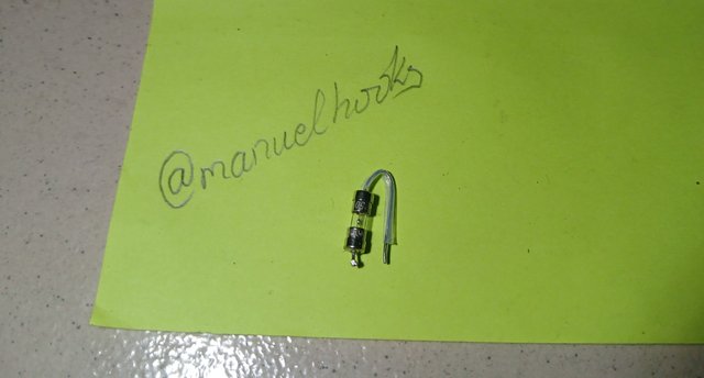
Step 1 [Identify the quantity]
The quantity is Continuity
Turn the function selector knob to CONT Y
Step 2 [Connect test probes]
Connect the black probe to -COM and the red prob to +
Step 3 [Identify the range to be used]
There is no range for this function
Step 4 [Test Expectation]
If all is well and the fuse is good, the Continuity light will light up.
If the fuse is bad , the light will not light up.
Step 5 [Connect probs]
Connect red to one side and black to the other side.
Step 6 [Observation]
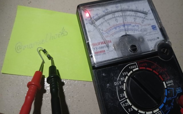
The Continuity indicator comes up once the probs are connected meaning the fuse is good.

Example 07:
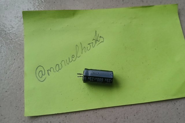
Testing an Electrolytic Capacitor
Step 1 [Identify the quantity]
The quantity to be measured is capacitance
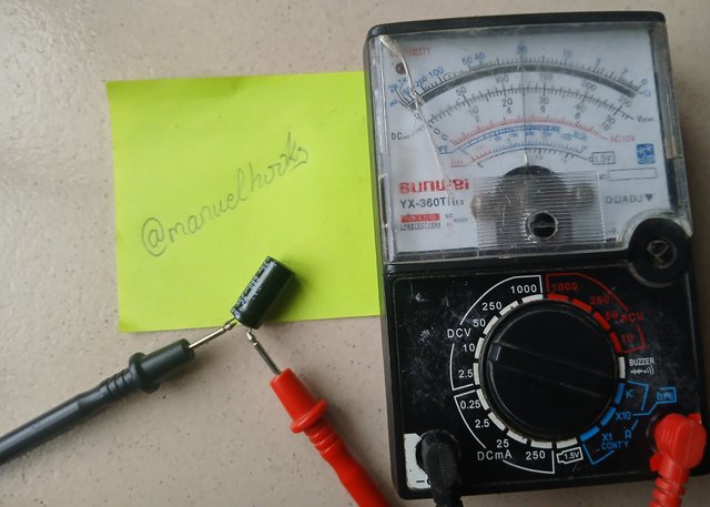
This model of multimeter has no function for capacitance and can not measure in micro farad. We will test by observing its charging behaviour. Turn the function selector knob to Ohmmeter Ω
Step 2 [Connect test probes]
Connect the black probe to -COM and the red prob to +
Step 3 [Identify the range to be used]
This capacitor is a 680uf capacitor so i will set it to kΩ
Step 4 [Test Expectation]
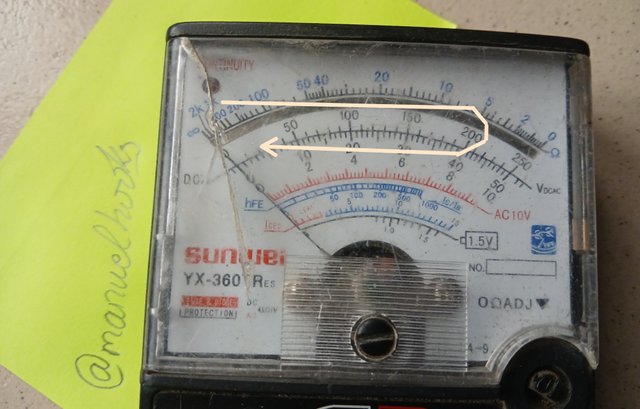
If this capacitor is good, the resistance value will eventually stabilize at a relatively low value (close to zero). And when fully charged, it should act as an open circuit taking the needle back to infinity.
Step 5 [Connect probes]
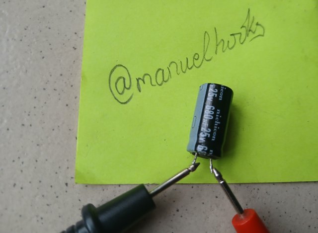
Place the red probe to positive end of the capacitor and the black probe to the negative end. The negative is the side with the strip.
Step 6 [Observation]
As expected, the needle moved down and at some point it smoothly started going back when the capacitor got fully charged
Workshop 2
A few tools we would use during the course of our weekly lessons.
Soldering Iron
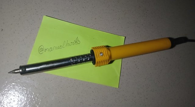
Used for desolving soldering lead, it will be used when removing components and when attaching it to a circuit board. Soldering iron comes in 60w, 80w and 100w.
Project Board
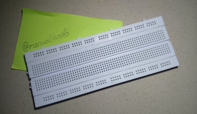
Helps to easily create a circuit with components that can be reused. The project board makes mounting of components very easy. With a project board, you can quickly test run a circuit.
Digital Multimeter
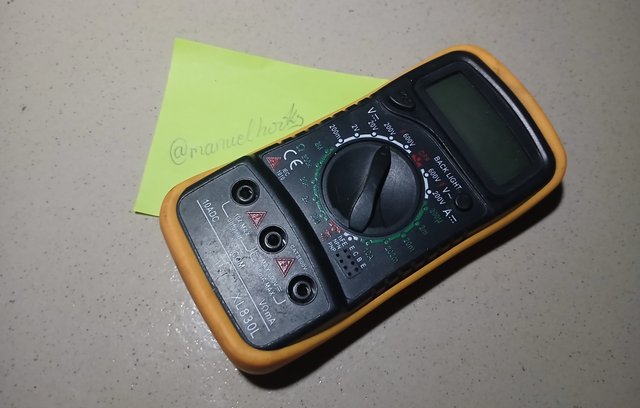
Used for measuring electrical and electronic quantities like voltage, current, resistance, capacitance, transistor gain,
Screwdriver
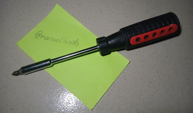
Electronic devices are often housed in an enclosure and will need a screwdriver to disassemble and reassemble the device.
Cutter
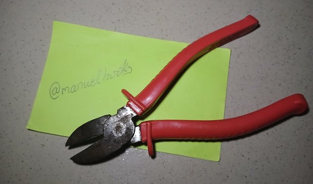
Cutters will come in handy when cutting and pealing cables.
Tester
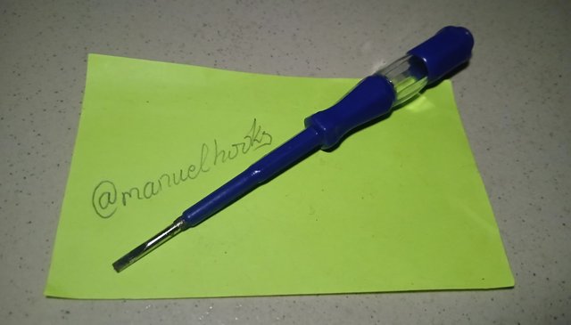
Used to quickly tell if a socket has power
Conclusion
Test equipment like multimeters comes in diffrent brands and models, some have very few functions. Some meters require a range setting while advance models automatically selects the range once the function is selected.
If your meter needs a range selection be careful not to under select a range as it may damage the meter, if you are not sure of the range, use the highest available range on the meter.
I am inviting @leonciocast, @simonnwigwe, @josepha and @udyliciouz to participate
#electronicss19w2 #steemexclusive #nigeria #burnsteem25 #electronics #club5050
Your task 1 experiments were all great. You've demonstrated how to test for both AC and DC voltage, resistance, continuity...., but you've missed capacitance.
The 6 tools you mention in task 2 are all useful, and would be used during this electronic classes. We have already mentioned
soldering iron, I wasn't expecting you to mention it again. There are actually other important ones as well and we were looking for "8 more"...
Comment/Recommendation
These are very good approach on each of the tasks.
The write up were simple and brief with only relevant information which can be useful to other students.
However, I noticed some typo, if you could fix those, that would be great.
Maybe, a very brief conclusion wouldn't be bad too as you had an intro.
Engage with other users in the Academy, we didn't spot your engagement last week.
Scores| 9/10
Downvoting a post can decrease pending rewards and make it less visible. Common reasons:
Submit
Thank you for the assessment, i have made the corrections and have applied the suggestions.
Please can we post electronic related post here in the community besides the official homework?
Downvoting a post can decrease pending rewards and make it less visible. Common reasons:
Submit
Due to how users flood communities with AI or plagiarised contents, we won't accept much written contents like that. Infact we are working on the community policies which we would post much later in the future.
For now, users should concentrate on the tasks.
If one is posting any content here it MUST be purely practical, with enough guides that can help other persons to follow, you have to show the steps with pictures or videos and as such, the aim of making here educational center would be achieved.
Example of such contents is what the professors are posting, these are just clues to students of what would be accepted in the future if the community is open for anybody to write other contents apart from the normal assignment tasks.
Here is purely for PRACTICALS or a kind of show working center, not for narration or a whole lots of write ups...
So for now, NO.
As a suggestion, maybe you could post that related electronic post that you wanted to post in your personal blog, you could tag me.
Downvoting a post can decrease pending rewards and make it less visible. Common reasons:
Submit
I hope you will pay attention to moderator @ubongudofot remarks!
Downvoting a post can decrease pending rewards and make it less visible. Common reasons:
Submit
You have done so well in this. I will be pleased to submit mine by weekend. Good luck to you
Downvoting a post can decrease pending rewards and make it less visible. Common reasons:
Submit
Thank you, I can't wait to read your homework this week.
Downvoting a post can decrease pending rewards and make it less visible. Common reasons:
Submit
Excelente participación amigo explicaste muy bien como medir correctamente cada componente y mencionaste seis componentes muy importantes para trabajar en la electrónica
Le deseo mucha suerte en su participación
Downvoting a post can decrease pending rewards and make it less visible. Common reasons:
Submit
Thank you very much, i appreciate your encouragement. I will endevour to do even better...
Downvoting a post can decrease pending rewards and make it less visible. Common reasons:
Submit
Greetings brother you done your job to complete this task perfectly. Each and everything is in full detail. I appreciate your hard work. These measurements help me a lot because I am a newcomer to electronics. These tools help us a lot in electronics to do different work. I wish you the best of luck. Have a nice day
Downvoting a post can decrease pending rewards and make it less visible. Common reasons:
Submit
You are welcome, we are all still learning and can learn from each other.
Downvoting a post can decrease pending rewards and make it less visible. Common reasons:
Submit
Great Post by you @manuelhooks, you have provided a comprehensive overview of electronics components and measurement instruments using an analog multimeter.
Your step by step instructions and pictures are really helpful for people like me who is not an expert in electronics world.
Thanks for sharing your expertise.
Downvoting a post can decrease pending rewards and make it less visible. Common reasons:
Submit