Hello my friends it's me drifter1! Today's post will be about the implementation of an Sequential Circuit in Multisim. We already did a good little Sequential Circuit in Sequential Circuits and in the Statetable Simplification Method, but I didn't showed you how you implement such a Circuit using JK Flip Flops instead of D Flip Flops. That's what we will do today, and that's why I call it Advanced Sequential Circuits. :D So, withour further do let's get straight into it!
Quick Introduction:
To make the post easier to understand and much more compact we will implement a specific Example Circuit, and we will get very in depth. Also, before starting out I want to point out some Tricks with which we will fill our Statetable. If you remember from Flip Flops a JK Flip Flop has 4 Cases.
JK Flip Flop Cases:
- J = K = 0, called Memory State, where it keeps it's previous Output/State
- J = K = 1, called Switch, where it inverses the Output/State
- J = 0, K = 1, where the next Output/State will be '0'
- J = 1, K = 0, where the next Outputs/State will be '1'
But, we will not fill our Statetable using those Cases, but with some that contain Don't Cares!
So, you have to remember (or keep somewhere) the following:
- When we stay at '0' then J, K = 0, X
- When we stay at '1' then J, K = X, 0
- When we transition from '0' to '1' then J, K = 1, X
- When we transition from '1' to '0' then J, K = X, 1
That's exactly how we will fill our Statetable!
To make things more interesting I will this time create a Sequential Circuit having a State Diagram, finding a State Table out of it, then finding the Boolean Expressions/Functions that are needed for the State "Variables"/ JK Flip Flops and the Output and lastly create our Circuit. So, let's get started!
Statetable from Statediagram:
It's pretty easy to create a Statetable out of a Statediagram. But, because we will use JK Flip Flops we will have to make a bigger Statetable this time that contains also informations for each and every JK Flip Flop in our Circuit!
The information for creating our Sequential Circuit is given to us by this Statediagram:

Making a Statetable out of it is not so difficult and it would look like this:
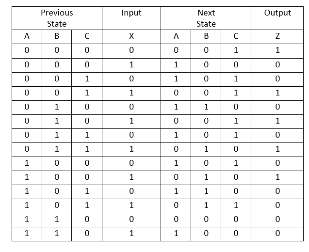
I simply added all the States (000, 001, 010, 011, 100, 101, 110) two times for each Input value (0 or 1) and then saw in which State we go in each Transition and what kind of Output we have, cause this time we have a Mealy FSM, where the Output depends on the Transition and not the State!
Each of the 3 State Bit's will be represented by a JK Flip Flop and so we will have to add 6 more Columns for all the 3 JK Flip Flops and their 2 Inputs J and K. We will check the specific Bit in the Previous and Next State of each JK Flip Flop and fill in the specific combination of J, K depending on this Bit. So, for example if we see that the previous State was 0 and the next one is 1 then we will fill in J, K = 1, X as I told you in our Introduction!
Doing that our Statetable will now look like this:
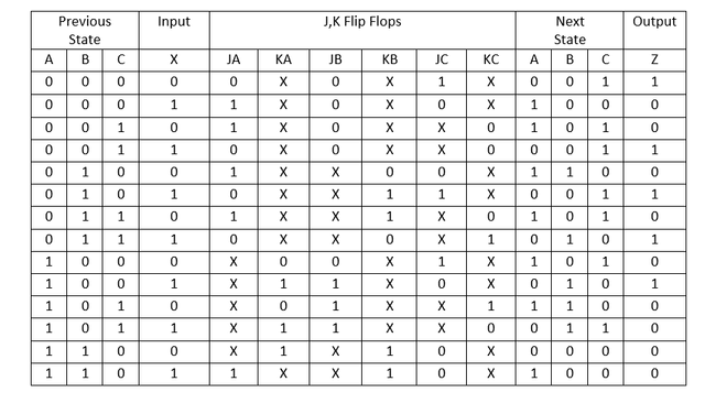
As you can see this Statetable is much bigger than the previous one, but using it our life will be made so much easier!
Boolean Expressions from Statetable:
This part is actually the same as before. The only thing that changes is that this time we have 7 things that we have to take care off that are the J, K of the 3 JK Flip Flops and the Output Z. If you remember from the D Flip Flop Implementation there we needed functions for the Next State that actually was the Input for each D Flip Flop and also a function for the Output again. So, this time we just have more Functions at the Inputs, cause the JK Flip Flops have 2 Inputs instead of 1 that a D Flip Flop has.
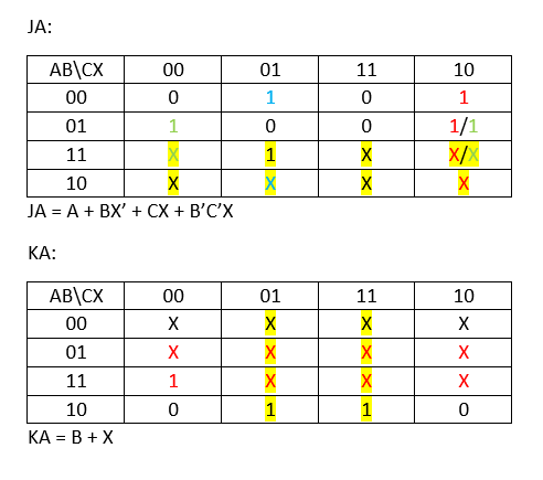
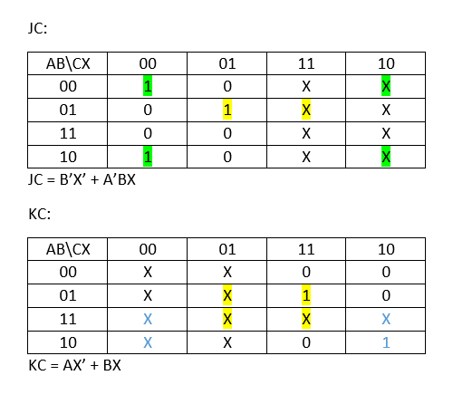
To get the Expressions in a simplified way we will use Karnaugh Map simplification for each of those 6 J, K Inputs and the Output Z. So, let's try it out.
For the first JK Flip Flop called A I have the following:
For the second JK Flip Flop called B I have:

For the last one called C I have:
The Output function will look like this:
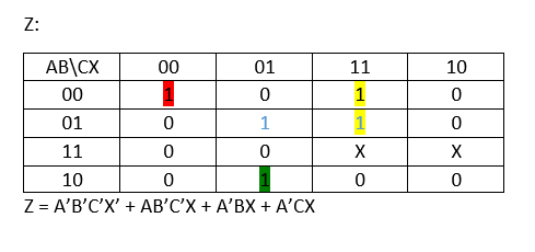
You can see that I managed to make the J and K Functions pretty simple by regrouping Minterms more than 1 times, so that I have the biggest possible Minterm Groups. The Output function in the other hand is pretty crazy and so we will use another way to not make our Circuit humongous!
Circuit from Boolean Expressions:
The Circuit in Multisim is pretty easy in Logic, but it will take a lot of time to combine all those Gates together! We will use 1 Switch for the Input X, 1 VCC to give it "power", 1 Clock for the JK Flip Flops, 3 JK Flip Flops, 5 Indicators from which 1 is for the Output Z and the others to check the Clock and JK Flip Flop values and many many Logic Gates to implement the Functions needed as Inputs for the JK Flip Flops.
Because the Output function didn't simplify so well, I will implement this function using a Multiplexer! We have 4 Inputs and so we have 3 Selection Lines and 2^3 = 8 "I" Inputs. So, we will need a 8-to-1 MUX.
Having A, B, C as Selection Lines and forgetting about the 111 Input, cause it's not a feasible Input we end up with the following "I Input" Array:
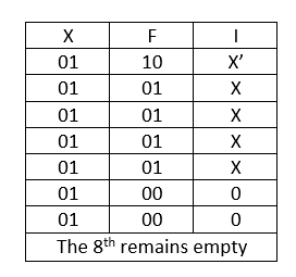
So, putting all this stuff together we end up with the following Sequential Circuit:

Yeah you can see that the Cable Management is the worst ever! But, I tested it out and it works right if you understand in which State we start! Try rebuilding it if you like to test out some State Switching by yourself.
And this is actually it! Hope you enjoyed it!
This is the Final Multisim I had planned to upload. From next time in Logic Design we will get into VHDL Coding! Starting off with some Basic Theory stuff you need to get started with Coding Circuits with this Language!
Until next time...Bye!
Congratulations @drifter1! You have completed some achievement on Steemit and have been rewarded with new badge(s) :
Click on any badge to view your own Board of Honor on SteemitBoard.
For more information about SteemitBoard, click here
If you no longer want to receive notifications, reply to this comment with the word
STOPDownvoting a post can decrease pending rewards and make it less visible. Common reasons:
Submit