Despite all the hard efforts to keep IT cables dry, water remains the most likely cause of cable failure. Water introduction into the cable leads to various types of damage, often resulting in a high-resistance short circuit.
Signs of cable water ingress change over time. Usually, the first symptom is the appearance of noise on the line. Interference occurs due to the flow of microcurrents between conductors. Suppose the service personnel do not take any measures. The problem may grow in that case, so communication will be blocked entirely. Cables with some water inside them can be categorized into two types: wet and waterlogged. Most of the time, the cable is simply soaked. In cables with filler, water can accumulate in existing voids and in overhead cables in sagging sections. In warm weather, it evaporates, and in cold weather, it condenses back again. As a result, the copper wires corrode, increasing resistance and causing poor cable performance.
Water ingress occurs when water penetrates the cable through a damaged jacket. In this case, the impact may come from groundwater, melting snow, precipitation, etc. A cable submerged in water may work normally until it inevitably does not.
SEARCHING FOR WATER INGRESS SPOTS
Water impact is found when the reflectometer detects a change in the resistance of the pair being tested due to a change in its capacitance. In addition, a good indicator can be the pulse propagation speed, which directly depends on the characteristics of the cable.
Water in the cable "slows down" the signal. In the waterlogged section, the electrical signal's propagation speed can change every other inch. As a result, measuring the actual length of the entire cable and its waterlogged section is much more challenging since the reflectometer measures time intervals. (The bridge meter will indicate that the cable length is longer than the actual length.) Water significantly increases the capacitance of the waterlogged section of the cable, so it will not be possible to find the correct propagation coefficient value. To reliably measure the cable length, one usually measures the length of a dry section, either on one or both sides. If the total length of the cable is known, subtract the lengths of the dry sections from it. Very often, the starting point of the waterlogged segment is too close to the reflectometer connection point. In this case, the device will not detect the presence of water. Therefore, the cable must be checked from both sides.
Some OTDRs have a "marker" function to measure the distance between two points, eliminating the need to measure dry sections on both sides of the cable and making it easier to determine the length of a waterlogged section.
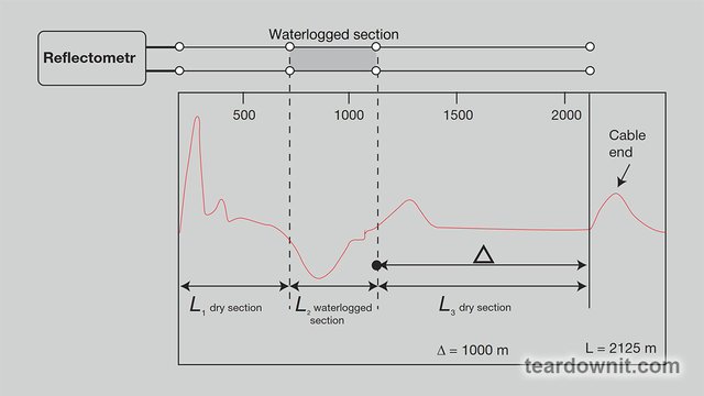
The figure shows that L2 = Lcable – (L1 + L3), where L2 is the known cable length and L1 and L3 are dry sections.
Water ingress affects the operation of multiple cable pairs. When testing a disconnected or inactive pair, there is a possibility that some voltage may be induced by neighboring active pairs, which is why most testing methods, such as using bridge meters, lead to distorted results. In such a situation, a reflectometer is the only device that will allow one to find the water damage point.
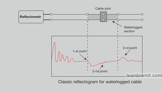
The classic reflectogram of a waterlogged cable has three key features. The first is a decline in the reflectogram (reflected pulse of negative polarity) in the place where the section of the waterlogged cable starts. The second is a waterlogged segment of the cable, usually having a slightly curved characteristic with "noise" (this is not noise per se, but simply an impedance unevenness that causes a characteristic distortion to appear on that section of the cable). Finally, the third is the rise of the reflectogram at the end of the waterlogged section of the cable (the reflected pulse of positive polarity). The reference reflectogram in the figure illustrates the ideal case.
It is important to emphasize that the water in the cable significantly weakens the reflectometer signal. If the waterlogged segment is too long, then the farther end of it can be indiscernible on the OTDR's display.
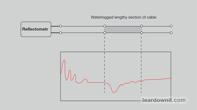
On a real reflectogram of a cable with water in the coupling, a signal is reflected both from the place of the cable coupling and the waterlogged section of the cable. It is quite difficult to notice initially, but increasing the gain level will make the reflectogram more straightforward.
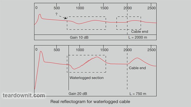
After increasing the gain level, it is much easier to see the classic decline in the reflectogram after the cable coupling (at a distance of approximately 2500 feet) and the uneven reflectogram for the waterlogged section of the cable (at a distance of about 2500–3000 feet). The reflectogram line goes up at the place where the waterlogged section of the cable ends (at a distance of approximately 3300 feet). In addition, the end of the cable can be clearly defined at 6500 feet.
TROUBLESHOOTING A WATERLOGGED CABLE SECTION
One of the most challenging tasks associated with troubleshooting using an OTDR is identifying faults in a water-damaged cable section. The reflectogram will indicate water ingress, but the locations of various faults are usually masked by distortions caused by the water in the cable.
The procedure for searching for damage in waterlogged cable sections using a reflectometer is shown above. It allows one to see the advantages of the differential measurement method in real-time.
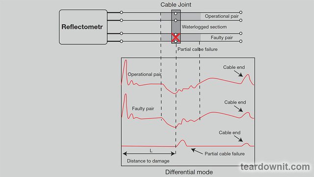
The reflectometer display will display the difference between the characteristics of the "good" and the pair being tested. Both pass through the same waterlogged section of the cable, so the water will not affect the final reflectogram; only the differences between the two pairs will remain on it. Once the display shows the location of the damage, one can measure the distance to it.
So, suppose there is a suspicion that water has gotten inside the cable, first of all. In that case, it is necessary to determine the location of the affected segment. The role of a reflectometer in quickly localizing where water enters a cable cannot be overestimated.