We know that the inductance and capacitance elements behave differently at different frequencies. The capacitor behaves like an open circuit at low frequencies, such as a short circuit at high frequencies, while the coil component behaves like an open circuit at low frequencies such as a short circuit at high frequencies. Then it can pass or stop according to the frequency of a signal using these elements in various combinations; we can set a lower limit or an upper limit for the incoming signal frequency.
Low Pass Filter

Comment:
As the frequency increases, the response of the capacitor begins to decrease, ie the impedance it starts to behave as a short circuit. In this case, the applied voltage shows itself more on the series connected resistance to the capacitance. That is to say, the input of the high frequency applied series R C is much higher than that of R because C has a very small impedance. As the frequency drops, the response of the capacitor increases, and the voltage read between the capacitive ends increases in value. We can use this selectivity to make a low-pass filter. In the meantime, the resistance shows the same reactivity at all frequencies.
Analysis:
Let's write the elements of the phasor domain.

We are the mark to see on the exit from the tension section Vout:

Equation is the angular frequency of the input signal W we see.
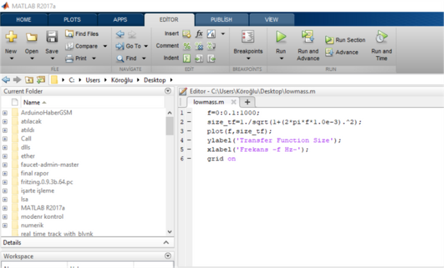
Open the MATLAB:

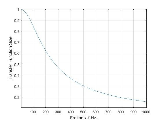
Graph when we print:

Let's also comment on the graph. As you can see, at a sinusoidal output of 10 Hz, the first magnitude is 0.988, which is almost like it is. At a sinusoidal output of 300 Hz, the first magnitude is seen at 0.46 magnitude, that is, it loses more than half of its magnitude.
Friends, we always talked about a single frequency signal, we did this to see the behavior of the filter. However, there are many frequency-bearing signals inside the filter, so what is the meaning of filtering! In multiple frequency-bearing signals, the filtration in each fre- quency is treated separately, and the result is again the sum of these separate results. For example, when we turn our talk into electrical operation, we see that there are many frequency components, and when we filter this signal with a low-pass filter, the high frequency components in the speech signal will hardly show themselves at the output and we will hear a thicker speech.
A clear statement of the behavior of the low-pass filter to remain in mind is shown in the picture below:

Thank you for all of your support!
İHSAN,