Custom thumbnail...
Introduction
Hello it's a me Drifter Programming! Today we continue with my small series, where we will be implementing a complete system in VHDL. Today's post is the 4th and final part of the series and so I highly suggest you to go and read all the previous parts first, where I explain and analyze the system and also implement most of the system in VHDL.
Today's post will be about:
- implementing the FSM as a component (step 3)
- writing a testbench
So, without further do, let's get straight into it!
Small Recap
In my previous posts we implemented the whole system that had to do with the following matrixmultiplication:

or

The result-element gets calculated as:

To make the AND operation and XOR happen in one single step we use an Accumulator that stores the previous result in a register and applies the XOR operation between the "current" and "previous" multiplication (AND) result. For the first calculation (of each column) the register gets initialized to '0' via a reset signal.
Step 3
So, let's get started with the 3rd and final step...
The previous two parts already "created" a finished system that works, but having the FSM be the "whole system" is not right and so we will change that today by making the FSM a component too. The FSM code is already large and by also putting the "connection" code inside of this file we end up with a very large FSM that just isn't right. This means that the actual structural representation (interconnection of the components) will be another VHDL file/entity that will "call" the rest and connect them together. Simulating the circuit in the 1st and 2nd step meant simulating the FSM. After all this changes that we will today, simulating will mean simulating the actual structural representation of the system. We of course will also create a testbench finally. Let's call this new entity vector_mul from "Vector Multiplication". This "new" entiyty will now have the inputs and outputs of the main system and the FSM will now have the corresponding needed inputs and also outputs, which will be the control signals.
FSM changes
To sum it up the FSM will now have the following inputs:
- Clock, Asynchronous reset (areset) and valid from before
- 3 addresses/counters, for A, H and R.
And the following outputs or control signals:
- rw_enableA and mem_enableA to control the behavior of RAM(A)
- count_resetA and count_enableA to control counterA
- rom_enableH to enable/disable ROM(H)
- count_resetH and count_enableH to control counterH
- accumulator_reset to manage the accumulator's initialization
- rw_enableR and mem_enableR to control the behavior of RAM(R)
- count_resetR and count_enableR to control counterR
You can clearly see that the main input and output of the system are not in the FSM anymore.
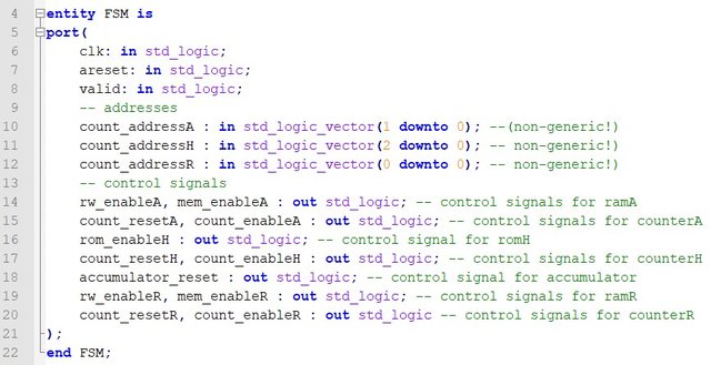
So, the ports of the FSM in VHDL are:
Top-level circuit (vector_mul)
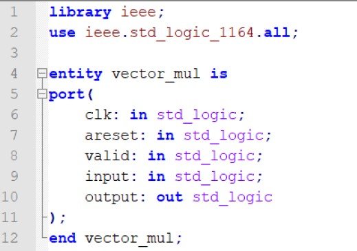
By having the "new" FSM already this new entity can be written very easily. The inputs/outputs are of course the same that the FSM had "before" and so:
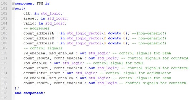
The architecture will of course also look similar in the "inter-connection" part. This means that the components and port-mappings will be exactly the same that the FSM had, but now the FSM will also be a component.
The FSM component is:
Before getting into the port mapping we should talk about the signals used to connect the components together...Well nothing special really...The signals are exactly the same that we had with the FSM being the "main" circuit and so:

Lastly, the FSM port mapping is:
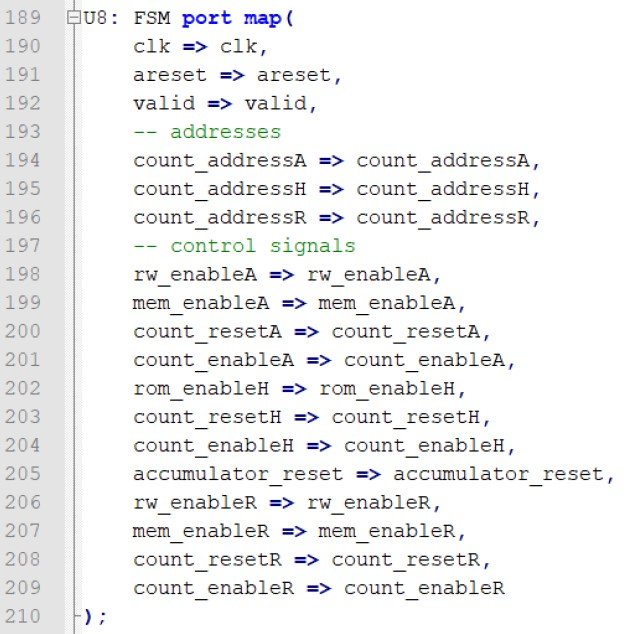
You can see that I put the same names for all the inputs/outputs and corresponding signals, so that it's much easier to "re-use" the previous code of the FSM that we had...
Testbench and simulation
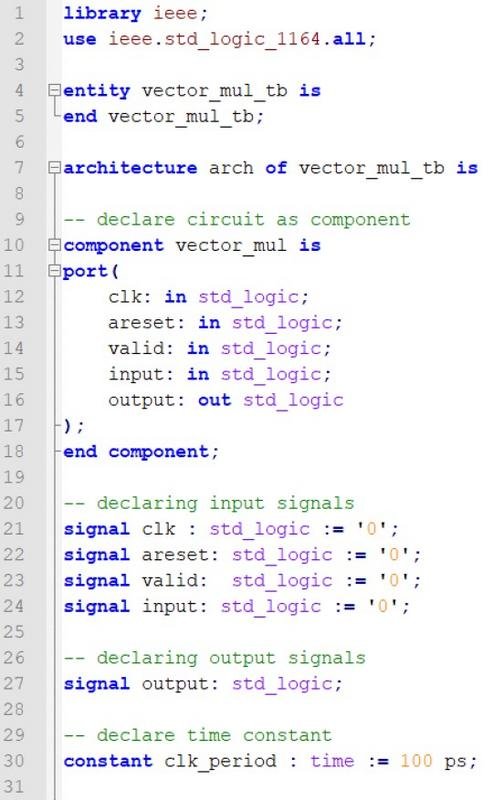
A testbench is a "port-less" entity that contains the main system (vector_mul) as a component. We define the inputs and outputs of the system as signals with the same name and also initialize the inputs to some value, let's say '0'. Because our system (like most systems) contains a clock we also define a time constant, which is the clock period. That way the first part of the testbench is:
After the "begin" we start by port mapping the component which we mostly call uut for unit-under-test, define the clock "simulation" process and then write a testing process, which will give values to the input signals. Let's say that we input "1111", but with an invalid '0' in-between. By inserting "1111" and having the ROM be the same as in the 2nd step we of course expect to see "10" as the result. The code for all that is:
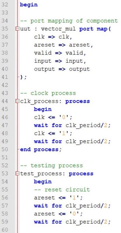
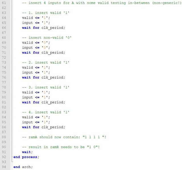
You can see that the "testing" does the following:
- reset the system for half a period
- run the system with no reset for half a period
- insert valid '1'
- insert non-valid '0'
- insert 3 valid '1's
- wait until the procedure is done...
Let's simulate the circuit in ModelSim to find out if it runs ok:

First of all we can see that RAM(A) contains "1111" and so the invalid '0' input don't got through. After that the calculation process starts. After finishing the "multiplication" RAM(R) contains "10" and the system outputs '1' and '0', which means that the system runs ok for these inputs!
One "united" counter
You might remember from a previous part of this series that I told you that we could also use one counter instead of 2 or 3...So, how exactly does that work? Well, the counter of R, A and H had the following lengths: 1, 2 and 3-bit. Because of the way that we are calculating the result the last 2 bits of counterH are exactly the bits of counterA. Think about it as following: counterH changes the first bit and goes to the "next" column and so start over from "00" in the last two bits. In the same way, the first bit of counterH is the same as the single bit of counterR. We have one result for each column and so each "column-switch" is equal to the current value of counterR. You can clearly see that it's possible to have one single counter for the whole system. The FSM will just need the corresponding bits for each counter and so the whole "new" counter for counterH (actually the "new" one is counterH, but just with a changed name), the first bit for counterR and the last 2 bits for counterA.
But, doing all these changes takes up some time, cause the control signals then need to be changed and the synchronization would become even much more difficult. Right now we can reset, enable and disable each counter individually. Think about the difference that it would make to have only one counter for everything...I already did that tho :P but, I will not give you the code, so just try and make it on your own as an exercise. Ha ha ha ha ha...
You can download the code for all the steps to play around in the following link:
References:
- For the mathematical equations I used quicklatex!
- The code is all written by myself (it's a task for my University)
Previous posts of this series
- Part 1 -> problem, analysis, software model, architecture
- Part 2 -> explaining how our architecture works, splitting the implementation in steps, implementing the storage step of vector A (step 1)
- Part 3 -> implementing the calculation and "printing" procedures
And this is actually it for today's post and this series. I hope that you enjoyed this series and that I helped you understand how we build a complete system in VHDL. This whole procedure is not that easy and a lot of simulation and testing is needed until you find the correct control signals for each state. Even the creation of an architecture might be a very difficult process sometimes...
C ya!