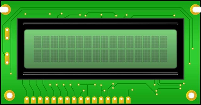
Pixabay Image : Liquid Crystal Display
Good day to you, my fellow steemians out there!. It's been very long you read my posts here right?
I'm fully back on my everyday watered down posts on electronics and embedded systems engineering.
Today, I will take my time to analyze one major electrical display module. The module is question is Liquid Crystal Display (LCD) module!
It's not something to doubt that one of the interesting parts of Embedded systems engineering is when the output from a microcontroller is being projected for the world to see (even the dangerous fire identifies itself via smokes).
The output could be as a result of the inputs from different sensors such as humidity, temperature, barometric pressure, light intensity, distance, gas level sensors etc, or as a result of deliberate actions by the project designer who would like to just let something show on a screen.

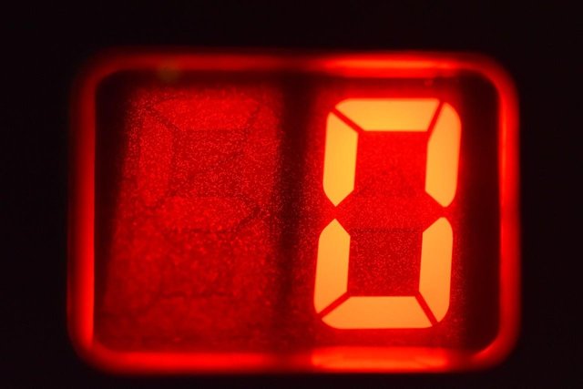
Pixabay Image: Seven Segment Display
There are two major modules for displaying outputs from microcontrollers, the first being a seven segment display and the second being a Liquid Crystal Display (LCD), but the latter is the mostly used among hobbyists and lovers of electronics as far as the matters relating to digital display of parameters are concerned. This is because LCD has etched its name in the display of both numeric and digital characters. Seven Segment or multi segment LEDs on the other hand can only show on its screen, numerical parameters.
OPERATIONAL PRINCIPLES.
A liquid crystal display works by using the light modulating properties of liquid crystals. The display is made up of pixels, each one filled with liquid crystals. These pixels are arrayed in front of a backlighting source or a reflector.
The crystals are placed into layers sandwiched between polarizing filters. The two polarizing panels are aligned at 90 degrees to each other, which blocks light. The first polarizing filter will polarize the light waves so that they all run in one orientation only. The second filter, being at 90 degrees to the first, will block the light. In other words, imagine that the filter is made up of very thin slits going in one direction.
Light polarized in one direction will go through slits in the same orientation, but when it reaches the second filter, which has its slits running the other way, it will not pass through. By running a current across the rows and columns of the layers, the crystals can be made to change orientation and line up with the electric field. This causes the light to twist 90 degrees, thus allowing it through the second filter. Hence, some displays are referred to as “Super-Twist.” The LCD is made up of a grid of pixels and these are arranged into smaller grids that make up the characters.
As the name implies, deep inside the device is embedded small amount of liquid. As such, the device mustn't be exposed to a very high temperature, which could evaporate the liquid, thereby damaging it. I would still explain this better in the rest part of the article. Cool right?
HOW DO I IDENTIFY DIFFERENT VARIETIES OF LCDs?
Liquid Crystal Display (LCD) comes in different sizes and colors combination. When talking about the sizes of the LCDs, I'm talking about the display strength of the device in terms of the number of characters it can project for the users to see. This display strength is denoted by M × N arrangement, with M being the columns and N being the row. Take for instance, a 16×2 LCD comprises two rows and each of these rows can display maximum of sixteen characters (space and alphanumeric). Other available LCD models are 16×4, 20×2, 20×4, 32×2, 32×4 etc.
Talking about combination of colors, there are many available varieties of LCD and they come in all kinds of colors. As an amateur robotics engineer, I particularly like the red on black displays (red text on a black background) because they preserve your night vision if used in robotics based projects.
There are also green on black Liquid Crystal Displays available in electronics shops. You can choose another color text and background but your display must have a backlight and be able to display the desired columns and rows of characters (often referred to as M×N LCD displays).
So, how do I make characters to show on a Liquid Crystal Display?
LCD-MICROCONTROLLER INTERFACING
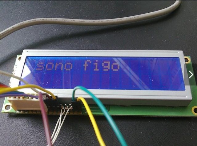
Liquid Crystal Display is a microcontroller on its own, so, characters aren't just displayed on it by chance. A microcontroller has been earlier explained in one of my previous articles as a computer (having input units, processing units and output units) operated on a single chip.
To make LCD functional for its display mission, it has to be connected to another microcontroller. This is what is referred to as the interfacing of LCD. Interfacing an LCD is by connecting some certain pins it's endowed with to that of the microcontroller. In this case, I'm using a PIC16F84A microcontroller.
Naturally, LCDs have sixteen pins. Four of the pins aren't to be used, Six of these pins are to be connected directly to the microcontroller pins and the rest six are to be connected to other specified pins (to be explained below). All these pins have their names already written on the LCD.

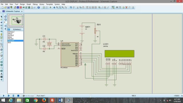
Interfacing LCD with microcontroller. Source: @thestronics
For a typical LCD display, the above circuit shows how it's being interfaced:
4-LCD PINS NOT TO BE USED FOR INTERFACING
D0: Data Pin 0
D1: Data Pin 1
D2: Data Pin 2
D3: Data Pin 3
Data Pins 0 to 3 are not used because you are going to use what is known as 4-bit mode.
6-PINS TO BE INTERFACED DIRECTLY WITH THE MICROCONTROLLER
RS : Register Select Pin
EN: Enable Pin
D4: Data Pin 4
D5: Data Pin 5
D6: Data Pin 6
D7: Data Pin 7
As shown above in the interfacing diagram, these pins only require direct connection with the controller.
6-OTHER PINS
VDD: Logic High Pin
VSS: Logic Low Pin
R/W : Read or Write pin
Vo: Contrast Pin
A: Anode Pin
K: Cathode Pin
VDD pin of the module is given a high logic level (+5V), VSS and Cathode pins are both given a low logic level (0V). The module can be read from and be written to. When you are to read from the module (which is exactly what this write-up is all about), you simply connect the R/W pin to a low logic level (0V).
The contrast adjustment pin on the LCD must be connected via a current limiting resistor in order to adjust the contrast the desired level. A value of around 10K ohm should suffice. If you find it difficult to get the right value, then connect a potentiometer (with value between about 4K ohm to 10K ohm) with the left leg to +5v, the right leg to ground, and the center leg to the contrast adjustment pin. Now you can use the knob to adjust the contrast until you can see the display clearly.
The Anode pin functions as the backlight. The backlight on most LCD required 4.2v, so you would add an appropriate current limiting resistor between +5v and the Anode Pin.
You could connect this anode pin to a PWM pin on the controller and use a PWM output to control the brightness of the backlight, but for simplicity’s sake you won’t use this method in this project.
PREFERENCES
THANKS FOR READING!!!


Congratulations @thestronics! You have completed some achievement on Steemit and have been rewarded with new badge(s) :
Click on the badge to view your Board of Honor.
If you no longer want to receive notifications, reply to this comment with the word
STOPDownvoting a post can decrease pending rewards and make it less visible. Common reasons:
Submit
Congratulations @thestronics! You have completed the following achievement on Steemit and have been rewarded with new badge(s) :
Click on the badge to view your Board of Honor.
If you no longer want to receive notifications, reply to this comment with the word
STOPDownvoting a post can decrease pending rewards and make it less visible. Common reasons:
Submit
Congratulations @thestronics! You have completed the following achievement on the Steem blockchain and have been rewarded with new badge(s) :
Click on the badge to view your Board of Honor.
If you no longer want to receive notifications, reply to this comment with the word
STOPDo not miss the last post from @steemitboard:
Downvoting a post can decrease pending rewards and make it less visible. Common reasons:
Submit
Congratulations @thestronics! You have completed the following achievement on the Steem blockchain and have been rewarded with new badge(s) :
Click here to view your Board of Honor
If you no longer want to receive notifications, reply to this comment with the word
STOPDownvoting a post can decrease pending rewards and make it less visible. Common reasons:
Submit
Congratulations @thestronics! You received a personal award!
Click here to view your Board
Downvoting a post can decrease pending rewards and make it less visible. Common reasons:
Submit
Congratulations @thestronics! You received a personal award!
You can view your badges on your Steem Board and compare to others on the Steem Ranking
Vote for @Steemitboard as a witness to get one more award and increased upvotes!
Downvoting a post can decrease pending rewards and make it less visible. Common reasons:
Submit