This invention is a development based on the interlocking plastic bricks (like LEGO bricks). It looks like a normal Lego brick except that it is equipped with a system to detect the configuration of what is built on it. It can help the child build very complicated shapes. The shapes could be from a catalogue that is provided by the factory or from the website of the company, it can store thousands of shapes.
Also, sometimes a child builds something considered by the child as complicated and hard to build, but what if the child wants to rebuild it later on, sometimes the child will not be able to build it again. This is where this invention is needed, because it helps the child build his/her previous complicated shapes.
So it has two options : 1) Building shapes from the factory. 2) Saving shapes built by the child and building them later on.
Introduction: This system is composed of 3 parts, the bricks (building blocks), the brick plate and a microprocessor. There is a total resistance in the brick plate which changes as we add a brick, that change can be used to determine the type of brick and its position. Adding a piece at a time, the toy will help the child until the total shape is finished. We need a brick plate equipped with resistors and a microprocessor, Also the brick needs to be equipped with resistors, It uses an Arduino microprocessor to calculate the position of the brick using the resistors mounted on the bricks and a brick plate. It will be shown how in the coming section.
Building the system: The system is built as follows: A)The bricks: The two pin brick (2×1) and the eight pin brick (4×2) will use the same technique as the four pins brick (2×2), so only the four pin brick is explained here because it contains the concept in general, the four pin brick is shown in figure 1. The only thing that is different from one brick type to another is the value of resistors used, so each type has a different value for the resistors. This is because we want the microprocessor to sense the different types of bricks.
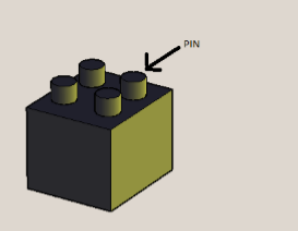
Figure 1
The resistors will be mounted inside brick in the configuration shown in the figures 2,3 and 4 There two sets of resistors that need to be mounted inside the brick, the first and second sets are shown in figure 2 and 3 respectively. In figure 4 the all brick resistors are shown together
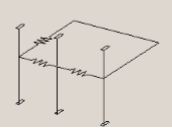
Figure 2
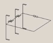
Figure 3
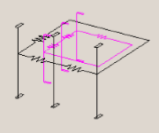
Figure 4
It should be noted that the contacts go to the top and the bottom of the brick allowing 3D detection by the microprocessor, also the two groups of resistors in figure 4 are not touching, also the contacts are drawn this way just for explanation, it will be longer in the real world, it goes from one side to the other .
B) The brick plate: The brick plate is constructed as follows as in the diagram, The horizontal resistors are shown in figure 5.
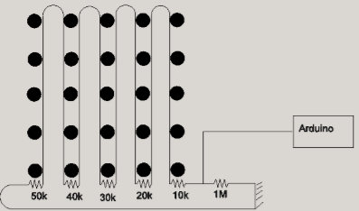
Figure 5
The vertical resistors are same as horizontal but tilted 90 degrees. The whole thing together is just putting the horizontal and the vertical resistors on top of each other without touching each other. Mounting the resistors here is the same as the building block we just put them inside, we then have to mount the contacts carefully in their positions. C)The microprocessor: There is a green light and red light if the position of the brick is right the green light turns on otherwise the red light is turned on, the microprocessor is programmed with the following algorithm: 1) The resistance of the plate resistors is measured and stored 2) After adding a brick to the plate, step one is updated and stored in a new place. 3) Comparing the new value and the old value of resistance we can determine the value of resistance added hence the type is known. 4) And also we get the value of the plate resistors connected to the brick, hence the position of the brick is known. 5) Store the new value of the plate resistance as “old resistance”. 6) Compare current shape to required (selected shape). 7) if shape is right turn on green light else turn red light 8) If shape is not complete repeat steps 2 to 6 each time we add a brick.
The whole system together:
First we need to mount resistors on the bricks.
Then we need a brick plate with resistors mounted on the edges as explained before. 3) Then we connect the plate resistors to the microprocessor as explained.
Then the microprocessor is programmed with the algorithm given to calculate the position of the brick in three dimensions.