Original creation date: 30th March 2017
Note: Originally I posted this on my Wordpress Blog (https://1337codersblog.wordpress.com), but I decided to switch to steemit, so I copied it from there.
Simple light barrier – Part 1
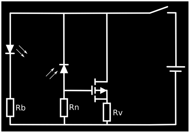
For a project I’m currently working on I need a light barrier. For maximum efficiency the light barrier should have a high resistance in idle state and in triggered state it should have a low resistance, because it will be most time in idle state. There were some building kits for light barriers in my favourite electronic shop, but they need too much space for my project so I need something more compact. Another point is that they use relays for switching which are too sluggish for my application, need too much electrical power and are too expensive for me because I need many of them. So I decided to design it own my own:

In Idle state, the light, emitted by the LED is being catched by the photo diode (can also be a photo transistor if necessary), so a high current flows through the photo diode and the resistor Rn. This results in a positive gate-source voltage of the p-chanel MOSFET, so it locks the current flow through the consumer Rv. For reducing enegy loss, the resistance Rn should be as high as possible. In triggered state, nearly no current flows through the photo diode, so the gate-source voltage of the MOSFET is negative, so the MOSFET will turn on and let the current flow through the consumer Rv. The resistance Rb is just a base resistance for protecting the LED from overvoltage.
I will build a prototype of this circuit at the end of this month and will post my test results on this blog.