What Will I Learn?
In this tutorial, the user will learn:
Design of a temperature meter with sound alarm, to measure the temperature of an industrial furnace.
Connection of: RHT03 temperature sensor, 16x2 LCD screen, potentiometer and buzzer with the Arduino Uno card.
System connection in breadboard using fritzing for real assembly.
Requirements
Basic knowledge of Arduino programming.
Basic knowledge of the operation of the RHT03 sensor and buzzer.
See the previous tutorials.
16x2 LCD screen
RHT03 sensor
Buzzer 5V
Potentiometer 20 kOhm
Arduino One card.
Difficulty
- Advanced
Tutorial Contents
Greetings, this is a contribution from @gasuba for Utopian of Open Source programs. In this opportunity, the temperature measurement of an industrial furnace will be exposed, which must operate to a specific range or desired temperature, in case the temperature variable exceeds the desired value a sonic alarm will be activated. Constantly, a message will be displayed indicating the temperature of the oven on the LCD screen. The input physical variable will be the temperature and humidity that is detected by the RHT03 sensor, which will send the sensed value to the Arduino card one and this will send the corresponding data for the message on the LCD screen and activate the buzzer when appropriate. It is always good to remember that fritzing allows us to make our connection diagram long before making a real connection, in the following figure the temperature measurement diagram including the sound alarm is shown:

Own source
It is important to mention that although the RHT03 sensor measures temperature and humidity, we will only use the temperature variable for the case of the oven.
Step 1.
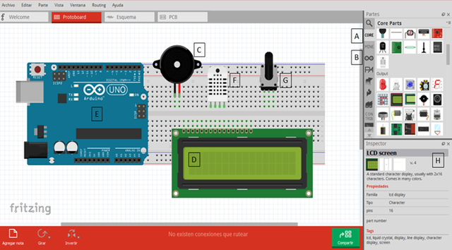
We select electronic devices for temperature measurement and alarm, these devices are: a 16x2 LCD screen (16 columns and 2 rows), the Arduino Uno acquisition card, the RHT03 temperature sensor and the buzzer. The figure shown below exposes the devices and the location in the fritzing window to find them:
A. Search of electronic devices.
B. Family of Arduino cards.
C. Buzzer.
D. 16x2 LCD screen.
E. Arduino Uno card.
F. Temperature sensor RHT03.
G. Potentiometer.
H. Description and configuration of each device.
Step 2.
The first stage of connection will be made with the 16x2 LCD screen with Arduino, in the image shown below, the schematic view showing fritzing is displayed to have the connection sequence. This screen consists of 16 pins that are described below:
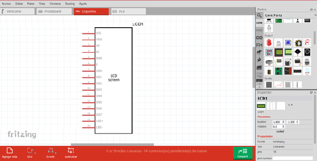
Vdd: Point in common with the Arduino card.
Vcc: 5V power supplied by the Arduino card.
Vo: LCD voltage operation connected to the middle pin of the potentiometer.
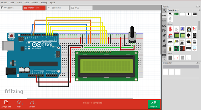
RS: Selection register connected to pin 12.
R / W: Reading and writing connected to the point in common with Arduino.
E: Enabling signal connected to pin 11 of Arduino.
DB4: Pin of data connected to pin 5 of Arduino.
DB5: Pin of data connected to pin 4 of Arduino.
DB6: Pin of data connected to pin 3 of Arduino.
DB7: Pin of data connected to pin 2 of Arduino.
Led +: Contrast of the LCD screen connected to Vcc.
Led-: Contrast of the LCD screen connected to Vdd.
In the image shown below, the connection of the LCD screen with the fritzing tools is observed, in addition to the Arduino programming that is shown at the end of the tutorial, the LCD screen is configured with the connecting pins that are linked with the card to show the temperature of the oven during the entire measurement process.
Step 3.
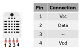
In this stage we connect the temperature sensor RHT03 and Loudspeaker. The temperature sensor is connected to pin 6 of the Arduino, it also has 4 connection pins as shown below:
Own source
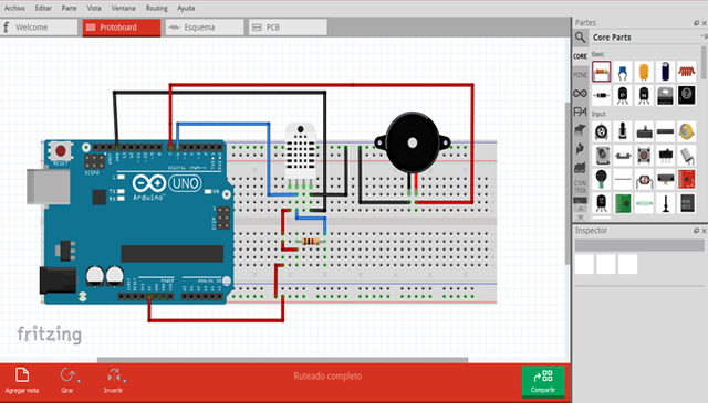
The following figure shows the connection of the temperature sensor connected to pin 6 of the Arduino, with a resistance of 1kΩ on pin 2. The buzzer is connected to pin 7 of the Arduino and will activate when the temperature value in the oven exceeds the desired value.
Step 4.
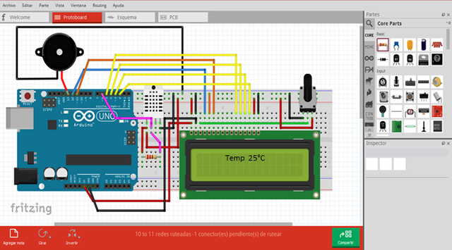
We make the final connection of all the devices that constitute the temperature measurement including the sound alarm, whose system is based on the RHT03 sensor, the potentiometer that is connected to the LCD screen allows to control the brightness of the screen, the buzzer will allow the user is alert to any change in temperature that is unusual. The connection is as follows:
Step 5
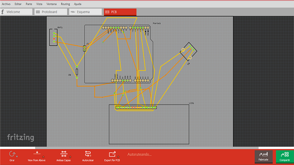
Finally, we obtain the PCB scheme of the system, whose tool of fritzing allows us to export our system to the plates where the real devices can be placed with all the tracks included, knowing that each track contains the continuity between the elements connected to each other. Observe the following figure:
The Arduino code is presented, to be recorded on the card and make the physical connection of all the devices for the pilot test, then we submit the temperature sensor in an oven and observe the application. It is important to mention that the DHT11 sensor library was downloaded, which has the same operation and connection as the RHT03 sensor. This last device is the one that fritzing has in its components, this allows us to simulate the DHT11 device connection, which we will program in arduino. Observe the code:
#include <LiquidCrystal.h>
#include <DHT11.h>

//Initialize bookstores
DHT11 dht11(6);
LiquidCrystal lcd(12,11,5,4,3,2);

void setup()
{
  dht11.begin(); //Initialize sensor communication and LCD screen
  lcd.begin(16,2);
}

void loop()
{
  //The variables temperature and humidity are declared
  float t;
  float h;
  dht11.read(h,t);  //Read the sensor measurements
  lcd.clear();// Clean LCD screen
  lcd.setCursor(1,0);  //Position the cursor to write on the screen
  lcd.print("Temp: ");  //Print the temperature label
  lcd.setCursor(1,1);
  lcd.print(t);  //Print the temperature value
  lcd.print(" C'");
             if (t>=110){
                digitalWrite(13, HIGH);  //Activate buzzer when the temperature is higher than 110 ° C
                }
                else {
                 digitalWrite(13,LOW);  //Deactivate buzzer when the temperature is lower than 110 ° C
                 }
 delay(500);   //Time to read new data
}
In the code we can see the inclusion of libraries: LCD and DHT11, the first Arduino contains it in its programming interface to include it and program it. In the case of the sensor library, it can be downloaded at the following link: DHT11
Thank you all for your time and attention, I hope it is very useful for your automation projects and smart devices ... See you in the next tutorial.
Curriculum
- Proximity detector with ultrasonic transducer and arduino using fritzing: Tutorial 3
- Access control with photoelectric using fritzing with Arduino: Tutorial 2
- Control of an alarm with LEDs and the Arduino Uno card using Fritzing: Tutorial 1.
- Introducción a Fritzing utilizando un circuito básico con LDR
Posted on Utopian.io - Rewarding Open Source Contributors
Congratulations! This post has been upvoted from the communal account, @minnowsupport, by gasuba from the Minnow Support Project. It's a witness project run by aggroed, ausbitbank, teamsteem, theprophet0, someguy123, neoxian, followbtcnews, and netuoso. The goal is to help Steemit grow by supporting Minnows. Please find us at the Peace, Abundance, and Liberty Network (PALnet) Discord Channel. It's a completely public and open space to all members of the Steemit community who voluntarily choose to be there.
If you would like to delegate to the Minnow Support Project you can do so by clicking on the following links: 50SP, 100SP, 250SP, 500SP, 1000SP, 5000SP.
Be sure to leave at least 50SP undelegated on your account.
Downvoting a post can decrease pending rewards and make it less visible. Common reasons:
Submit
Your contribution cannot be approved because it does not follow the Utopian Rules.
Related Rule:
Clarifications and Suggestions:
You can contact us on Discord.
[utopian-moderator]
Downvoting a post can decrease pending rewards and make it less visible. Common reasons:
Submit