Hello everyone! This is my first contribution in the field of electronics and technology. Since I am an electronics engineer, I would like to impart my knowledge about PIC programming that I had learned during my college days. This step by step process in making 8 LED light pattern is a basic programming that you can apply when you want to make a Christmas lights in your home. It only depends in your style, in your pattern & the design of light pattern that you want to see. For those who love electronics and technology, I hope you will find it interesting.
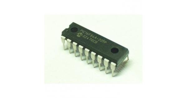
Let’s start with the materials and software that we will be using in this topic
Materials
♦Push button
♦Capacitor
♦Crystal oscillator
♦LED light
♦PIC16F84A
♦Resistor
Software
◘Proteus 8 professional
◘MikroC compiler for PIC
Now let us know about our materials and its usage
push button
A push-button or simply button is a simple switch mechanism for controlling some aspect of a machine or a process.
capacitor
A capacitor is a passive two-terminal electrical component that stores electrical energy in an electric field.The effect of a capacitor is known as capacitance. While some capacitance exists between any two electrical conductors in proximity in a circuit, a capacitor is a component designed to add capacitance to a circuit. The capacitor was originally known as a condenser.
Crystal oscillator
A crystal oscillator is an electronic oscillator circuit that uses the mechanical resonance of a vibrating crystal of piezoelectric material to create an electrical signal with a precise frequency.
LED
Light-emitting diode (LED) is a two-lead semiconductor light source. It is a p–n junction diode that emits light when activated.
PIC Microcontroller
The acronym PIC stands for "peripheral interface controller," although that term is rarely used nowadays.
A microcontroller is a compact microcomputer designed to govern the operation of embedded systems in motor vehicles, robots, office machines, medical devices, mobile radios, vending machines, home appliances, and various other devices. A typical microcontroller includes a processor, memory, and peripherals.
Desired Output LED Light Pattern
Pushbutton1: 01010101
Pushbutton2: 10101010
Pushbutton3: 00001111
Pushbutton4: 11110000
Pushbutton5: 11111111
Note: “1” –Lights on
“0”—Lights off
How to Program a PIC Microcontroller
Microcontroller programming means coding of a microcontroller for different purposes in special software. There are lots of software in which we can write different codes for microcontroller and IC Chips. But in this session, we will use the mikro C programming.
Below, we will discuss that how to program a microcontroller. In this tutorial, we will program or write a simple code for PIC16 microcontroller in C where “C” is a widely-used computer language and it happens to be the only supported language (aside from assembly) at this time for 8-bit and 16-bit PIC microcontrollers.
8 bit PIC:
PIC10, PIC12, PIC16, PIC18 are series of 8bit MCU.
How to burn a coded program to the microcontroller
Burning a microcontroller means to transfer the coded program from the compiler where compiler is a software where we can write, analyze, test and debug the coded program for a microcontroller, to the microcontroller memory. The coding or program written for microcontroller is generally in assembly/C language and the compiler generates a hex file which is understandable by the microcontroller. The hex file contains special instructions which are to be transferred to the microcontroller memory and then it works according to the given instruction and program.
Below are the simple steps tutorial to understand the programing / simple coding and burning a microcontroller.
When we programmed a microcontroller (we will discuss the step by step tutorial on how to program and write the special purpose coding for a microcontroller), then we need it to burn this program to the memory of the microcontroller. For this purpose, we need a hardware which understand and read the contents and programming codes of the hex file stored on our laptop or PC via software. So we connect this hardware via USB cable or serial to the PC/Laptop and transfer the written programming code to the memory of microcontroller and then microcontroller perform the exact function for which the designer and manufacturer designed the microcontroller IC Chip.
Programming PIC16 Microcontroller in C
Microchip Technology is the 2nd largest electronics and IC fabrication industry. Microchip Technology sells microcontrollers in 6-pin packages (PIC10F2xx series) , 100-pin packages (dsPIC33EP512MU810) and even 144-pin packages (some PIC32 devices). Also, there are many previous series like PIC12, PIC16, PIC18.
Introduction to the PIC controller that we will be using
The PIC16F84 is the most well known and most well used of all the PIC microcontrollers - it is used in numerous projects that you can find across the web.
Even though the 16F84 is getting on a bit, it is one of the most popular of the PIC microcontrollers and there are hundreds of circuits for it on the web but it does have limited memory, RAM and peripherals (See diagram below). As of 2015 microchip are recommending that you use 16F84A instead of 16F84 with the only difference being that the A-version runs at 20MHz using a 20MHz crystal (the non-A version runs at 10MHz crystal speed only).
Introduction of the Programming Environment
The programming environment we are going to use is MikroC for PIC. This IDE is fully equipped with a range of built in libraries and easy to use interface. This integrated development environment is packed with many calculators like hex to binary and decimal conversion which helps a lot in programming. This Software size is also very small as compared to other software so it is easy to use and install. The Syntax of this software is a little Bit different then MPLAB Software but being a designer, I will suggest all the reader to use MikroC instead of MPLB because of it really easy to read syntax and lots of built in libraries to use. It will definitely reduce the programming time and you don’t have to build the common functions from scratch like delay, LCD read and writes, RS232 Protocol and lots of others.
Part I: MikroC compiler for PIC
Step 1: Open the MikroC programming software
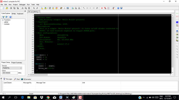
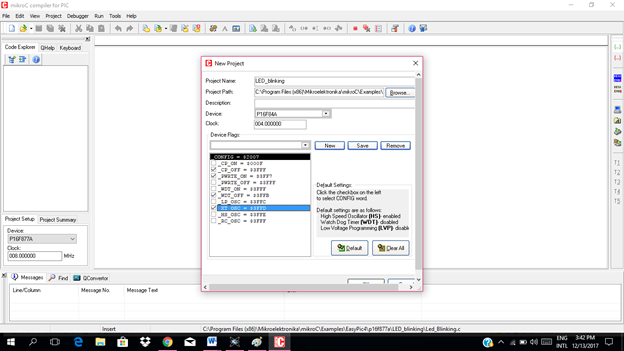
Step 2: Now go to the Project button in the upper right corner and click “Project”.
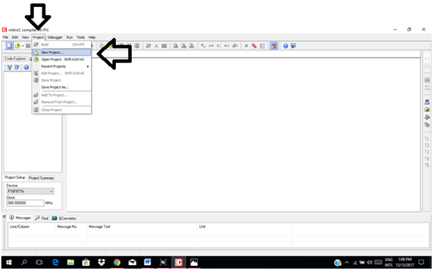
Step 3: Now click on “New Project” and new window will appear.
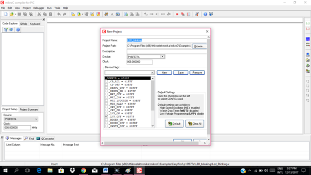
Step 4 Set up the parameters of the project:
Project name, project path (the folder where you want to save the project), the device used which is the PIC16F84A , the clock which is 4 Mhz.
Check the necessary configuration as you can see in the picture. After that click save then click ok.
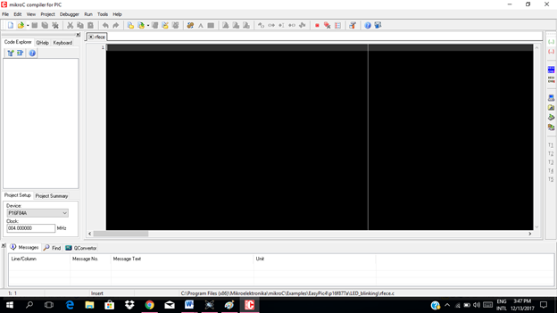
Step 5. Now this is our programming Environment. On this window we have to write code and compile it. Now we have setup the software. Next step is writing code.
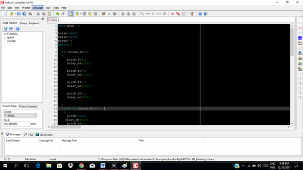
These are codes that i was made for this tutorial
void main ()
  {
     trisb=0x00;
     trisa=0x1f;
     portb=0;
     while(1)
  {
     if (Porta.f0==1)
  {
  portb.f0=1;
    delay_ms(500);
     portb.f2=1;
    delay_ms(500);
    portb.f4=1;
    delay_ms(500);
    portb.f6=1;
    delay_ms(500);
}
 else if (porta.f1==1)
  {
    portb=0x00;
   delay_ms(500);
    portb.f1=1;
   delay_ms(500);
    portb.f3=1;
   delay_ms(500);
    portb.f5=1;
   delay_ms(500);
    portb.f7=1;
   delay_ms(500);
  }
 else if (porta.f2==1)
  {
  portb=0x00;
   delay_ms(500);
   portb.f0=1;
   delay_ms(500);
   portb.f1=1;
   delay_ms(500);
   portb.f2=1;
   delay_ms(500);
   portb.f3=1;
   delay_ms(500);
  }
  else if (porta.f3==1)
  {
   portb.f7=1;
   delay_ms(500);
   portb.f6=1;
   delay_ms(500);
   portb.f5=1;
   delay_ms(500);
   portb.f4=1;
   delay_ms(500);
  }
 else if (porta.f4==1)
  {
   portb=0x00;
   delay_ms(500);
   portb.f0=1;
   delay_ms(500);
   portb.f1=1;
   delay_ms(500);
   portb.f2=1;
   delay_ms(500);
   portb.f3=1;
   delay_ms(500);
   portb.f4=1;
   delay_ms(500);
   portb.f5=1;
   delay_ms(500);
    portb.f6=1;
   delay_ms(500);
    portb.f7=1;
   delay_ms(500);
  }
}
}
In writing Code for PIC16 Microcontroller:
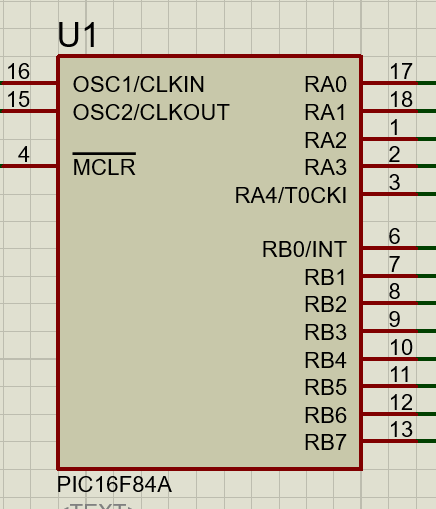
Making a port as input or output:
Each port has TRISX Register which defines that you are using this port for the input or for output.
Where X can be, A, B, C, D, E, F e.g. TRISB.
For output you have to put 0x00 in TRISB and for input you have to put 0xFF in it.
But this is not always the case because each pin can be independently selected as an input or output.
You could write 0x09 to TRISB which would select RB0 and RB3 for inputs and the rest of the pins for outputs.
Delay function:
In mikroC I have selected the delay library so I don’t have to create the delay functions.
Here I can simply use Delay_ms() function.
In this function you have to give how many mili seconds delay you want like if you want 1000 mili second delay you can write it like Delay_ms(1000).
Since we are done writing the code we have to compile it.
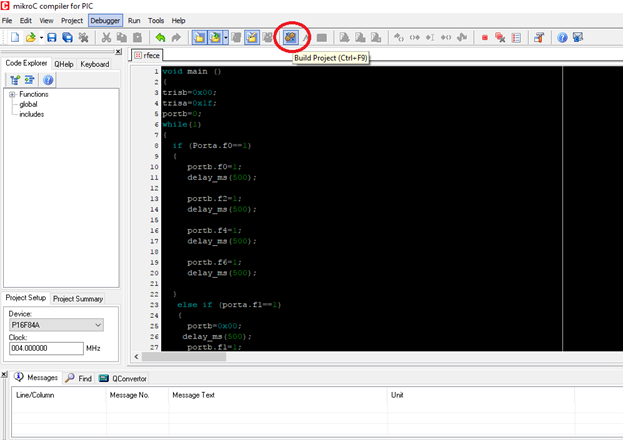
Click on this “build project “button code will be compiled and hex will be created in the folder in which you have saved your project file.
Once the hex is created you can burn this hex in your PIC16F84A by using PICKIT hardware or you can test it by using proteus.
But in this tutorial, we will use Proteus 8 professional in order to test our project before using it.
Part II: Proteus 8 professional
Step by step process in burning the hex file of our project to the PIC16F84A using Proteus 8 professional
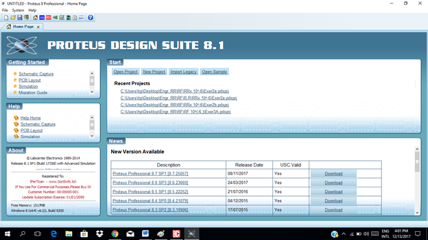
1. Let’s open the proteus. Let us assume that we already constructed our circuit .
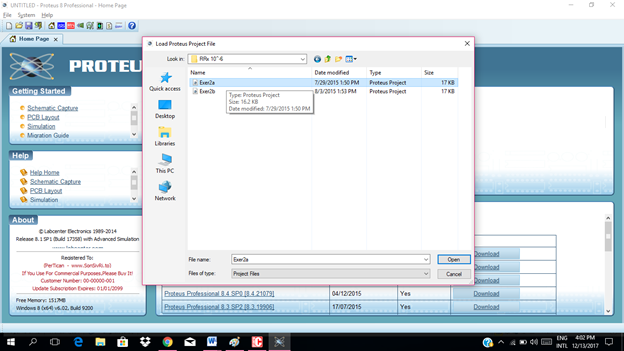
2. Open the circuit file.
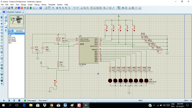
3. Double click the PIC16F84A
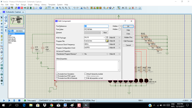
4. Select the hex file of the project then click "ok" to embed the code to the PIC16F84A.
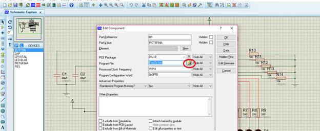
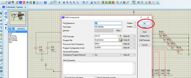
5. The final part is to run or simulate our circuit. Click the run icon below. Then we can try to press each push button that we had to see if it really works according to our written code. And make our conclusion.
Push button 1
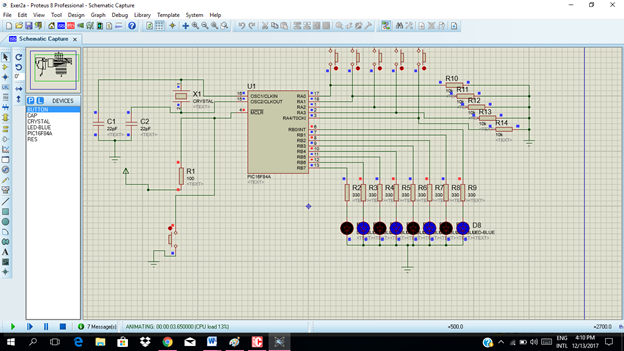
Push button 2

Push button 3
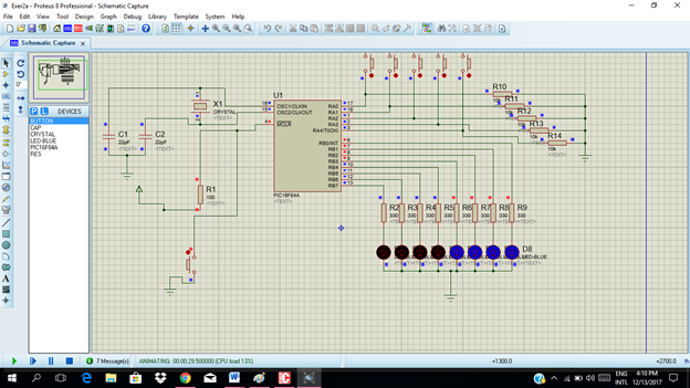
Push button 4
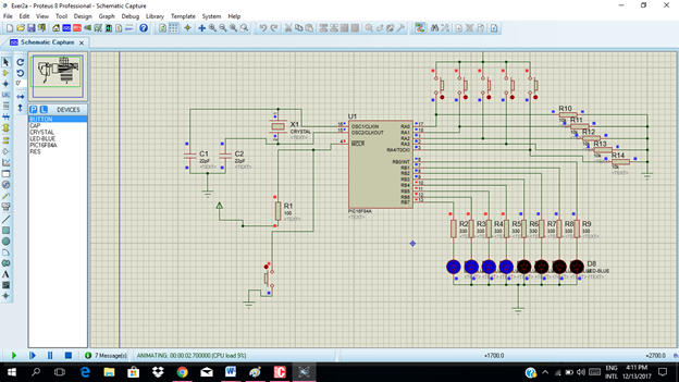
Push button 5
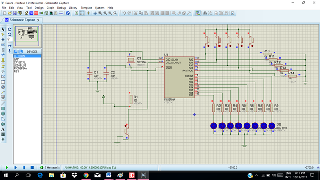
Conclusion
Our desired output pattern was achieved. Based from our simulation. The code is correct and it is ready to be burn in the PIC16F84A.
Importance and application of Microcontroller in our daily life
Through microcontroller, we can control different operations of various machines in our industry according to our desired output. In fact, our food that we eat, products and devices that we see were being processed through the use of a microcontroller. Microcontroller is widely use in mobile phones, auto mobile, DVD players, security camera and a lot a more.
# Is it nice to know basic PIC programming?
Well, I hope you can find it more interesting as our technology today advances to a level that we hardly cope up.
Thanks for dropping by.
Next tutorial I will use seven segment display.
Posted on Utopian.io - Rewarding Open Source Contributors
nice post @ rfece143... resteemed :)
Downvoting a post can decrease pending rewards and make it less visible. Common reasons:
Submit
Your contribution cannot be approved yet. Please enclose all the code in a code box using triple ticks (```). Please check any markdown formatting guide available online.
See the Utopian Rules. Please edit your contribution to reapply for approval.
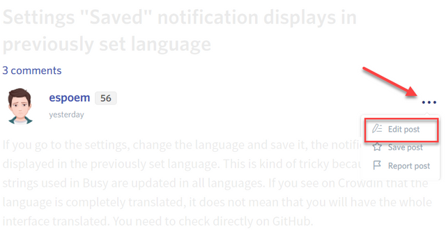
You may edit your post here, as shown below:
You can contact us on Discord.
[utopian-moderator]
Downvoting a post can decrease pending rewards and make it less visible. Common reasons:
Submit
Thank you so much @shreyasgune for giving me a chance..I already edited my post.
Downvoting a post can decrease pending rewards and make it less visible. Common reasons:
Submit
Very good post, quite detailed.
Downvoting a post can decrease pending rewards and make it less visible. Common reasons:
Submit
wow thank you @rpsreal ..im glad you like my post
Downvoting a post can decrease pending rewards and make it less visible. Common reasons:
Submit
Thank you for the contribution. It has been approved.
You can contact us on Discord.
[utopian-moderator]
Downvoting a post can decrease pending rewards and make it less visible. Common reasons:
Submit
Wow, thank you so much @shreyasgune ..
Downvoting a post can decrease pending rewards and make it less visible. Common reasons:
Submit
Hey @rfece143 I am @utopian-io. I have just upvoted you!
Achievements
Suggestions
Get Noticed!
Community-Driven Witness!
I am the first and only Steem Community-Driven Witness. Participate on Discord. Lets GROW TOGETHER!
Up-vote this comment to grow my power and help Open Source contributions like this one. Want to chat? Join me on Discord https://discord.gg/Pc8HG9x
Downvoting a post can decrease pending rewards and make it less visible. Common reasons:
Submit