
Hello my friends! Today we get again into VHDL to make a more analytic Example of an FSM. We will implement the FSM and simulate it in Modelsim and also create a Testbench for it afterwards! So, without further do let's get started!
FSM Diagram:
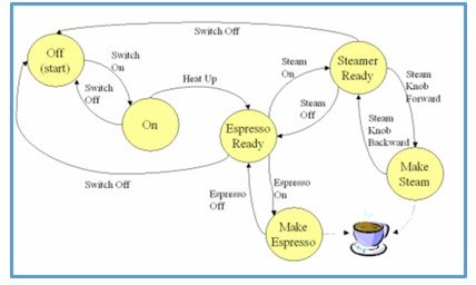
You can see that we are talking about Coffee machine. Each Vertex is a State and the Arrows/Edges define the Transitions. So, we will make States with names of Letters and also change the Arrows with 0/1 values.
That way our Diagram looks like this:
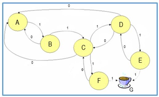
Using this edited diagram we can now easily make a FSM. G is the Final State as you can see and we also don't know if is is a Mealy or Moore FSM and so I will make it a Moore FSM so that each State has a specific Output.
To make our FSM more interesting we will add a Condition for going from F or E to G. To go to G from F or E we will need to have been to both F and E! This will be implemented easily in the Code in a minute.
FSM Coding:
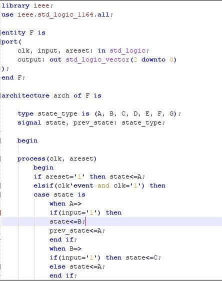
As always a FSM needs an clock input and this FSM also needs a asynchronous reset to set A to the start State, a input for the transitions and a 3-bit output for the State.
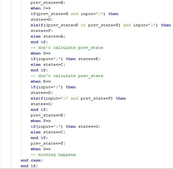
We will define our own StateType with letters A...G and a signal of that type. To check the Condition we will also include a prev_state that will get the value of the previous state in all transitions except those to C or D so that when going to E after going to F the previous state will be F and vise versa, and that way we will be able to go to the final state G.
We will check if the areset signal is '1' in an if statement and set A to the current state and else check if we are in a positive-edge clock event to start our transitions depending on the input and state!
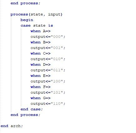
The Transitions will be checked in an Case statement as always and we will simply also check for prev_state = E or F for going to G when we are in F or E. We will also have a separate process that sets the Output value for the current State!
So, our Code looks like this:
Let's now also simulate the Circuit in Modelsim:
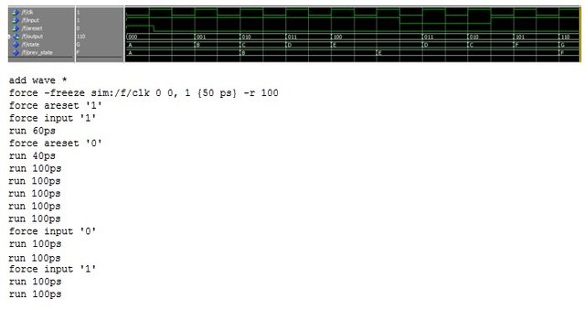
You can see that we started out reseting and so making our start state A. We then got to E going through B, C and D and then returned to C through D to go to F and then to the final State G. Doing that our condition was true, cause we have been to E before going to F and so we could go to G without any problem.
Testbench:
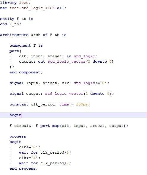
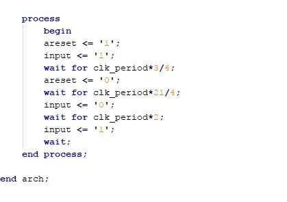
The Testbench will simply do the same assignments and runs/waits as we did in our manual simulation! We will first rest our Circuit and afterwards follow the transitions with the correct inputs to go to E return to C and then get to F and lastly G!
So, our Code looks like this:
Let's also simulate it with Multisim:

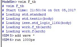
You can hopefully see that we got the exact same results as before, but only needed to run our testbench! Using this concept you can now create and simulate any FSM and also write it's testbench! I think it was a much better idea to put this example separately to the FSM post, cause that way we got more in depth into this one example and put the theory stuff aside!
And this is actually it and I hope you enjoyed this post!
Steemit's post system just can't take Code and always removes and edits stuff after posting and so I made pictures of the Code inside of Notepad++ and put the Pictures into the post, cause else you would have the wrong Code! Here are the links for the Codes in pastebin as unlisted:
I have a lot more to show in VHDL and the stuff that will do next time in VHDL will be even more interesting. I have already spoilered what we will do and so I wish you good luck searching for it!
Until next time...Bye!
Congratulations @drifter1! You have completed some achievement on Steemit and have been rewarded with new badge(s) :
Click on any badge to view your own Board of Honor on SteemitBoard.
For more information about SteemitBoard, click here
If you no longer want to receive notifications, reply to this comment with the word
STOPDownvoting a post can decrease pending rewards and make it less visible. Common reasons:
Submit