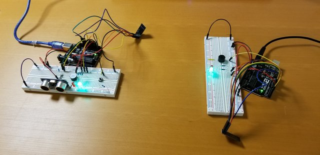
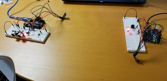
Description: Ultrasonic alarm system
Arduino 1:
- As a person comes closer to the ultrasonic sensor, an active buzzer will ring with higher frequency. The LEDs will also turn from green, yellow, to red based on the object's distance from the ultrasonic sensor.
- When the person reaches the red zone, RF module will send an alert to Arduino2.
- Person has to put the pass code in by pressing the buttons predetermined times. If the pass code is correct, the system will disarm.
- When the system is disarmed, the RF module sends disarm signal
Arduino 2:
- When the intrusion alert is received, a passive buzzer will ring. Red LED will also light.
- When the disarm signal is received, the green LED will light.
Components Used:
Arduino 1:
- HC-SR04 ultrasonic sensor
- NRF24L01 RF module
- Green LED
- Yellow LED
- Red LED
- 1kOhm resistor - to limit current to US sensor
- Switch button
- 10kOhm resistor - pull down resistor for the switch button
- 220kOhm resistors x 3 - LEDs
- Jumper wires
- HC-SR04 ultrasonic sensor
- NRF
Arduino2:
- NRF24L01 RF module
- Passive buzzer
- Green LED
- Red LED
- 220k resistors x 2 - LEDs
- Jumper wires
Safe Range

Danger Zone

Code:
Arduino1:
Arduino2:
Notes:
- HC-SR04 ultrasonic sensor can return noisy data depending on the shape / material of the object (ex: wrinkly clothes vs paper)
- NRF24L01 module need to be on 3.3V. 5V will destroy the circuit
- Controlling the frequency of the active buzzer turned out to be a non-trivial task as the default PWM using analogWrite() has a fixed frequency of 500Hz. The funcion only changes the duty cycle. Delay() is one option to change frequency. However, with many other dependent parts, using delay() function isn't feasible as it would also cause delay in other processes. I implemented the 'state machine' as a solution (see reference below).
- CSN pin of the RF module is susceptible to the OUTPUT of adjacent pin. When the TRIG pin (OUTPUT) was connected adjacent to the CSN pin, the RF modules could not communicate. Only after I moved the TRIG pin to other pin, the modules were able to communicate.
- Need pull down resistor with a pass code button and a de-bouncing mechanism
- Used software de-bouncing recommended in Arduino documentation, but better to use hardware de-bouncing method using RC de-bouncer.
- Powering the Arduino with USB port yields different results than powering with 9V battery. When powered with a new battery, it worked. The first battery had already been drained from previous projects. I learned that Arduino drains 9V battery fast. For best results, use USB cable or DC adaptor.
Resources:
Debouncing
https://pubweb.eng.utah.edu/~cs5780/debouncing.pdf
https://www.arduino.cc/en/Tutorial/Debounce
HR-SR04 sensor
https://components101.com/ultrasonic-sensor-working-pinout-datasheet
NRF24L01
https://arduino-info.wikispaces.com/Nrf24L01-2.4GHz-HowTo
9V battery as Arduino power supply
https://cybergibbons.com/uncategorized/arduino-misconceptions-6-a-9v-battery-is-a-good-power-source/
Changing pulse width modulation frequency
https://www.arduino.cc/en/Tutorial/SecretsOfArduinoPWM
My implementation of buzzer frequency
https://learn.adafruit.com/multi-tasking-the-arduino-part-1/using-millis-for-timing