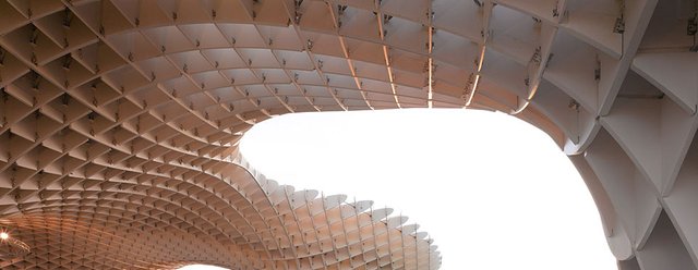
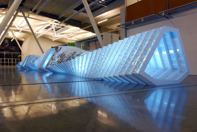
Orthographic projections—that is, plans and sections—are one of the most valuable representational tools architects have at their disposal. They are an indispensable communication and design device. They have also contributed to a prominent digital fabrication method. With computer modeling, deriving sections is no longer a necessarily two-dimensional drawing exercise. In fact, it is no longer an exercise in projection at all but a process of taking cuts through a formed three-dimensional object. As architects increasingly design with complex geometries, using sectioning as a method of taking numerous cross sections through a form has proven time and again an effective and compelling technique. As in conventional construction processes, information is translated from one format to another to communicate with the builder—only in this case the builder is a machine.
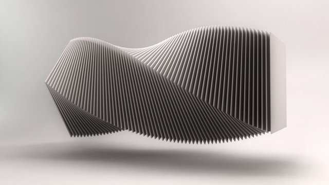
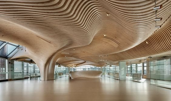
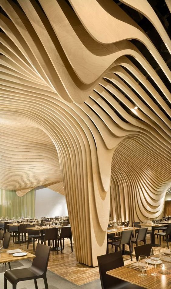
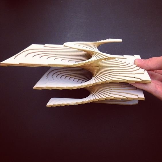
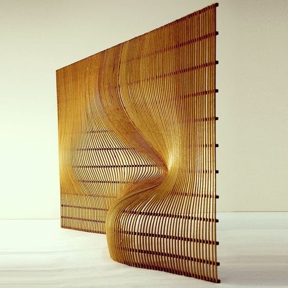
Rather than construct the surface itself, sectioning uses a series of profiles, the edges of which follow lines of surface geometry. The modeling software’s sectioning or contouring commands can almost instantaneously cut parallel sections through objects at designated intervals. This effectively streamlines the process of making serialized, parallel
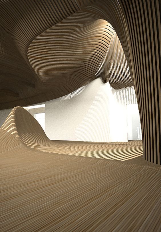
sections. Architects have experimented with sectional assemblies as a way to produce both surface and structure.
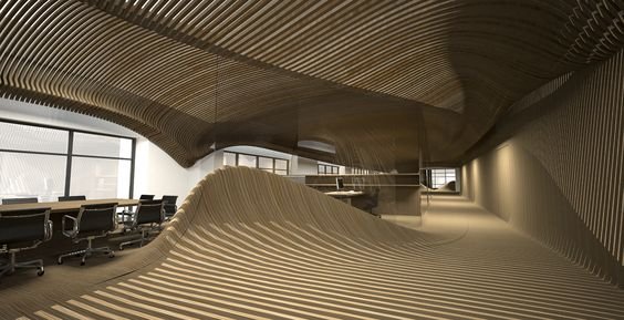
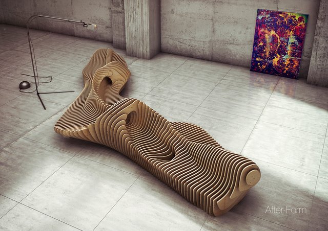

While it is distinctly within the domain of digital techniques, sectioning has a long history in the construction industry. It is commonly used in airplane and shipbuilding to make the doubly curving surfaces associated with their respective
built forms. Objects such as airplane bodies and boat hulls are first defined sectionally as a series of structural ribs, then clad with a surface material. Lofting—the method that determines the shape of the cladding or surface panels by building between
curved cross-sectional profiles—is analogous to lofting in digital software. Lofted surfaces can be unrolled into flat pieces or else geometrically redescribed in section as curves along the surface.
This building technique was adopted in the predigital era by architects such as Le Corbusier. The roof of the chapel at Ronchamp, for example— likened to an airplane wing by the architect—is designed and built as a series of structural concrete
ribs, tied together laterally by crossbeams. A paper model of the roof clearly shows the intentions for the internal construction. The advantages of using this type of hollow construction are clear: it is a lightweight structure that provides accurate edge
profiles for a nonuniform shape on which to align and support surface material, in this case thin shells of concrete. In his book Ronchamp, Le Corbusier enumerates the unique constructional makeup in a manner that recalls the makeup of digitally
constructed projects: “Seven strong, flat beams, 17 cm. thick, all different.”
Source: Digital Fabrications. Architectural and Material Techniques by Lisa Iwamoto
Wow looks great, i saw something similar in a hotel in croatia.you should be in the same room to get a real feeling
Downvoting a post can decrease pending rewards and make it less visible. Common reasons:
Submit
Cheers @lasper , was it the reception area or rooms?
Downvoting a post can decrease pending rewards and make it less visible. Common reasons:
Submit
Reception of course. In Croatia there are a lot of hotels but not futuristic ones
. This was accidentally put on the reception by someone
Downvoting a post can decrease pending rewards and make it less visible. Common reasons:
Submit
cooooooooooolllll
Downvoting a post can decrease pending rewards and make it less visible. Common reasons:
Submit
Cheers @damirekb , follow is you are into design ;)
Downvoting a post can decrease pending rewards and make it less visible. Common reasons:
Submit
Hi! I am a robot. I just upvoted you! I found similar content that readers might be interested in:
https://issuu.com/papress/docs/digital-fabrications
Downvoting a post can decrease pending rewards and make it less visible. Common reasons:
Submit
Thanks Robot, for helping my followers :)
Downvoting a post can decrease pending rewards and make it less visible. Common reasons:
Submit
Love this!!!
Downvoting a post can decrease pending rewards and make it less visible. Common reasons:
Submit
@jason.cooper11 Many thanks. Follow for more soon
Downvoting a post can decrease pending rewards and make it less visible. Common reasons:
Submit