
Title
Board Level Drop Test Reliability of IC Packages
Introduction
Portable electronic devices are prone to accidental drops during use. This led to concerns of failures in electronic components of these devices due to drop impact. The mechanical shock generated from a drop is transmitted to the printed circuit board (PCB) and the IC components mounted on the PCB inside the housing. The flexing between PCB and IC components during drop impact loading results in stresses in the solder joint and mechanical failure.
This paper study about the effect of board design, the failure mechanism and the board level drop impact performance of two types of common IC packages namely QFN and CSP, when subjected to JESD22-B111 test methodology. A test board named 2-layer PCB is developed based on equivalent dynamics to that of JESD board. Both the ENIG and OSP pad surface finishes have been considered for the test board. For the solder materials, SnPb eutectic and SAC 405 Pb free solder have been used. Finite Element Analysis (FEA) of the stress and strain fields during drop impact of the IC packages were performed and verified experimentally.
Methodology
The 2-layer PCBs are fully populated with 15 components with single sided assembly. Then, the PCB assembly was mounted with the package facing downward on a base plate that is fastened to the drop table of an AVEX shock tester with a standoff of 10 mm in Fig 2.
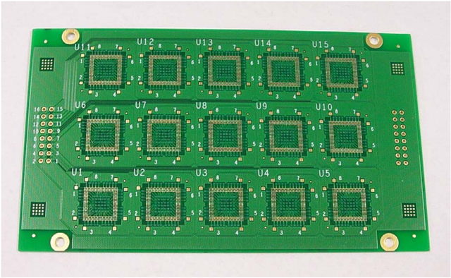 Fig 1: Sample of 2-layer test board
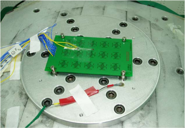 Fig 2: PCB assembly mounted on drop test table
This was inline with expectation that the horizontal board orientation will be the worst orientation case for drop failure. An accelerometer is attached near the support post on the base plate to measure the generated shock pulse of the drop tester. For the purpose of the test, the JESD recommended Condition B (e.g. 1500 G, 0.5 millisecond duration, and half-sine pulse) was adopted. For board monitoring, a uniaxial strain gauge was attached to the board center. Additional accelerometer may be placed next to the strain gauge for board acceleration monitoring during drop test. The drop test was continued until failure was detected.
 Table 1: Test matrix for drop test
Results and Discussions
The failure was found to occur not in the first acceleration peak or the board bending but after a few cycles of board bending. To further verify the failure mechanism, several strain gauges were placed at different locations on the board. This includes the package edge, package center and one on the package itself. The largest board deformation was found to occur at package edge region (refer to Fig 3). It is believed that the local deformation near the package edge has resulted in higher bending stress in the solder interconnection, hence leading to the failure there.
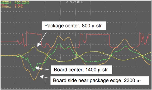 Fig 3: Board response with different strain gauge
All the samples shown in Table 1 were subjected to tests for 30 drops. The QFN samples with both SnPb and SnAgCu solder have shown no failures up to 30 drops while the CSP groups were found to have varying degrees of failure depending on its pad finish and solder materials type. Of all the samples, the ENIG pad finish was found to have the worst performance especially when it was used together with SnAgCu solder.
Some of the samples were subjected to further drop test in order to reveal the drop-to-failure distribution. In all cases, the center packages located along the transverse direction was found to fail sooner than package located in other areas as shown in Fig 4.
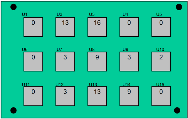 Fig 4: Distribution of cumulated number of failures for CSP
To have a better understand, further board response characterization were performed by measuring the board strains and accelerations at location U3, U6, U7 and U8. It was found that U3 always have higher strain and acceleration values compared to U8 during a drop test. Two types of failure mode have been observed: a) broken metal line near pad region for all the OSP finish sample and b) brittle intermetallic fracture of CSP solder joint at the board side for all the ENIG pad finish samples.
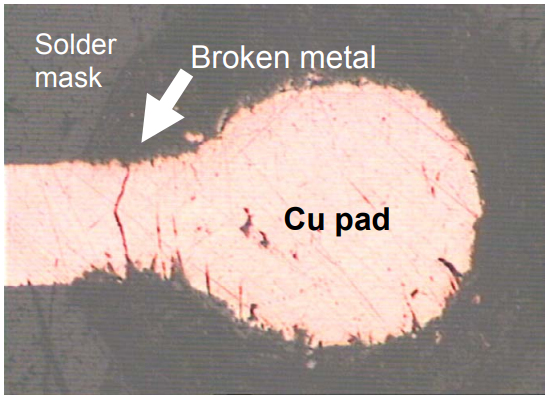
Fig 5: Broken metal line failure
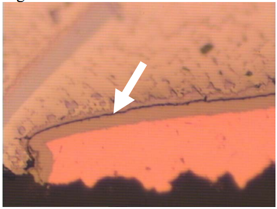
Fig 6: Brittle intermetallic fracture
Finite element analysis (FEA) was carried out to further investigate the drop test failure for CSP and QFN samples. From the 3D model, the maximum stress was found to occur on the metal line connected to the NSMD pad at the package corner region pad especially along the longitudinal direction of the PCB, as shown in Fig 7. This finding is in good agreement with the experimental results discussed earlier, with respect to the location of failure and the failure mode.
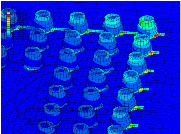
Fig 7: Stress distribution for CSP package
To investigate the critical package location on the board, maximum and minimum strain distributions on the board subjected to drop test are studied. From Fig 8, it can be seen that both maximum and minimum strain occurred at the upper corner of package U3 instead of at location U8.
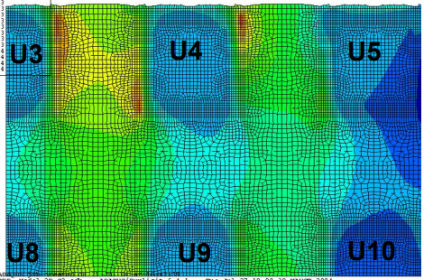
Fig 8a: Distribution of maximum strain on board
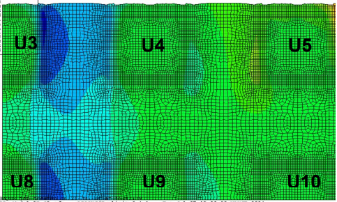
Fig 8b: Distribution of minimum strain on board
Conclusion
- A methodology of low cost board design based on an equivalent dynamic consideration has been developed.
- Smaller package like QFN was found to have better resistance to fail in board level drop test.
- ENIG pad finish was more susceptible to drop impact failure than OSP finish, especially when it was used together with SnAgCu solder.
- FEA modeling techniques for board level drop impact test were developed and validated on the CSP and QFN packages.
- The results obtained from the FEA matched with experimental responses.
Reference:
- Chai, T. C., Quek, S., Hnin, W. Y., Wong, E. H., Chia, J., Wang, Y. Y., ... & Lim, C. T. (2005, June). Board level drop test reliability of IC packages. In Electronic Components and Technology Conference, 2005. Proceedings. 55th (pp. 630-636). IEEE.