
What a topic to enhance and broaden our understanding of the whole system of power supply, its type, components and role of these components in ensuring the smooth running and efficient operation of the desktop which is linked to the computer. This is a picture of me and my desktop, ready for operation. I use this medium to appreciate the mentor of this learning challenge for giving us broad details before the assignment.
 | My desktop and I |
|---|
Examine the power supply unit of your computer or any other device and determine its type. Then, refer to the label on the unit to identify and note its input and output voltage specifications |
|---|
For this task, I'm told to do a close examination of the power supply unit of my computer. To do this close examination, I need to know where the power supply unit is in the computer. I uncoupled my computer using a star head screwdriver and removed the part covering this metal box.
The power supply unit is already explained in the course of the given tutorial and has types, varying the type of device used. After uncoupling the desktop, I saw a label on the power supply unit box where the input current and output current flows in and out of the device.
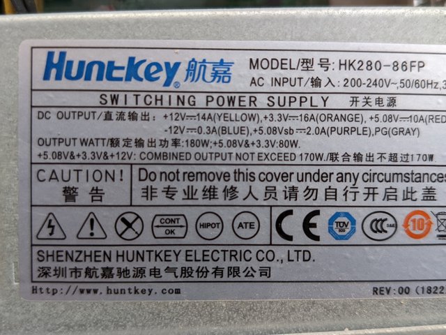
On the label has lot of writings which includes voltage, colours, watts, amperes etc.This level has a stern warning not to remove the label at any cost. So now that we have identified that this is a power supply unit box, how do we know the type? The type is different from models as the same type of power supply can have different models.
On this power supply unit, I'm seeing switching power supply which is the same as the switched power supply. Now, I can't say this power supply unit isn't an ATX which is a major type of power supply because ATX power supply works for most desktop computers and we're dealing with a desktop computer.
So the desktop I'm operating on has a ATX power supply which has specific connectors that matches some components in the desktop and the ATX motherboard. But why is is called a switching power supply?. Note, not all switched power supplies are ATX but this particular switched supply model is ATX as explained above.
Why it is called switching power supply is because the power supply uses a switching mode power supply system to efficiently convert electricity, which reduces heat and waste. It switches electricity on and off at high speed levels compared to other power supplies. It's just like having phone chargers with different shapes and sizes. Despite the sizes and shapes, all uses USB. The ATX is like a size and standard for desktop power supplies which sees to it the power supply fits into the standard for desktop power supplies.
The switched mode is like a car that stops at traffic lights to conserve fuel. It's more efficient tham an engine that always run, which is not as conserving as it should be. This applies to power supply unit. Switched mode power supplies efficiently control the flow of electricity. The technology here is a switching one while the ATX follows the standard size used in desktop computers and its connections. We can have a 20 pin or 24 pin DC outage in ATX power supplies.
So I've been able to identify the type. It's an ATX power supply that is a switching mode power supply. They aren't the same but falls under the category of having ATX as part of its types. That's the reason I didn't outrightly say it's direct switched power supply because an ATX power supply is used by most desktops and the specifications shown is evident in the desktop I'm working on.
| Type | ATX power supply [Switching mode power supply] |
|---|---|
| Model | HK280 – 86FP |
| Company Name | HuntKey |
Every electrical device needs a certain amount of electricity or specification to run properly. If power supply doesn't match the requirements of a particular device, it can cause overheating or damage. This is the reason why you see different watts, ampere and voltage running through these power supplies which I just sourced.
The difference is clear as the electricity requirements of these devices are different to fit the standard, capacity and size of the desktop to avoid malfunctioning or overheating. You can't carry 50kg bag of cement and give someone that's 30kg to carry. His weight must match the weight of the object or exceed that of the object otherwise he'll break down because of the capacity of the load.
For example your purchased a charger that has 5V. The amps should be at least 2A to function properly otherwise when high voltage is supplied, it could blow off the charger head. The current measures the capacity of the charger. If a charger can't provide enough current, charging would be very slow but if it does, charging would be fast and regulated.
For this desktop, I'll start with the AC input. The AC input Known as alternating current input is where electricity passes into the power supply, regulating electricity which then passes out through the DC, which is the direct current through the connectors or pins.
| Voltage | Frequency | Amps |
|---|---|---|
| 200-240V | 50/60Hz | 3A |
The 200-240 voltage is a range it can accept for electrical pressure in a device. If you read the voltage of a socket and it's 400 V, it could damage the charger plugged in because it's above normal. The voltage level is bad. This is actually the perfect range for a good voltage. The frequency having a range of 50-60 tells how fast electricity flows in and out while the 3A tells how much current the device can take to avoid overheating. The total output power is 180W after the conversion of alternating current power to direct current. This falls in the output section which I'll provide.
| Voltage | Amps | Colour |
|---|---|---|
| +12V | 14A | Yellow |
| +3.3V | 16A | Orange |
| +5.08V | 10A | Red |
| -12V | 0.3A | Blue |
| +5.08sb | 2A | Purple |
| Pz | - | Gray |
| Combined output not exceed | 1702W | - |
These are the specifications of my power supply from the lebel. Each of them matches itself to a pin which colour tells you the voltage and ampere it carries.
ATX power supplies supply power to ATX cards through a 24-pin connector. List the wire colors used for each number in the following table. |
|---|
First of all I want to say that the supply on my own end is through a 20-pin connector, consisting of wires of different colours. One may actually feel that these colours are irrelevant or unimportant but the importance in their colours is that they carry specific voltage which controls the outflow of electricity from the power supply.
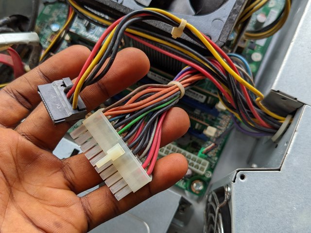
It's just like giving numbers to students with different uniform colours. This number and their colours are embedded in your mind. Now, let's say just the numbers are presented before you to identify the colours, it would be easy, having known that red house or blue house is 3 and that Yellow house is 7. It's more like this scenario.
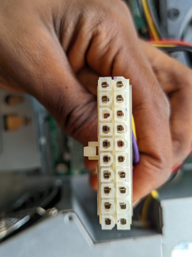 | 20-pin ATX connector |
|---|
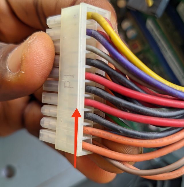
Numbers are given to identify the colours and these aren't just ordinary numbers. They are voltages each wire carries. Now, we have our 20-pin connector and the pins are numbered from 1 to 20. It is in your place to know which one is number 1, either the top or bottom or left and right sides.
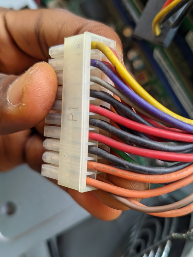
The little expo I'll give is that for you to determine this properly, check your connector for a bridge that looks like a nozzle. Now, it's not on the top or bottom of this part, so you'll have to turn to the other side that looks flat and check your bottom left to start counting from I hope you grab this expo?
 |  |
|---|
Now let's go into the main labelling of the pins and identification. The pin, voltage or power and their colours
| 1 | +3.3V | Orange 🟠 | 11 | +3.3V | Orange |
|---|---|---|---|---|---|
| 2 | +3.3V | Orange 🟠 | 12 | -12V | Blue 🔵 |
| 3 | GND | Black ⚫ | 13 | GND | Black ⚫ |
| 4 | +5V | Red 🔴 | 14 | PS.ON | Green 🟢 |
| 5 | GND | Black ⚫ | 15 | GND | Black ⚫ |
| 6 | +5V | Red 🔴 | 16 | GND | Black ⚫ |
| 7 | GND | Black ⚫ | 17 | GND | Black ⚫ |
| 8 | PW.Ok | Grey 🩶 | 18 | -5V | White ⚪ |
| 9 | +5.08Vsb | Purple 🟣 | 19 | +5V | Red 🔴 |
| 10 | +12V | Yellow 🟡 | 20 | +5V | Red 🔴 |
Since I was told to list only, I'll not need to go in-depth in explanation. The first and second pin from behind if the bridge is by your left has the colour orange with some other pins listed below.
- 1, 2, and 11....Has that orange colour 🟧of wire which carries 3.3 volts of electricity which carries power at different voltages used for powering components of the motherboard like the RAM etc.
- Black colour ⬛ seems to be common and had the numbers, 3, 5,7,13,15, 16 and 17 The black wire colour indicates ground wires which helps stabilise voltage and completes the circuit. It seems to be much more than other colours in their respective pins.
- Grey wire colours 🩶 says power is good. It gives a signal to the motherboard that the power supply is working perfectly. Without this signal, the computer boot well. It is only one on the 20-pin connector.
Red 🟥 on a normal case means live wire but in the case of this DC supply, these wires supply 5V needed by the USB ports and other storage devices including the motherboard. It's seen in pins 4,6,19 and 20.
The 5.08Vsb means +5V standby which indicates purple colour 🟪 wire and allows some power to be available when the computer is off.
- The yellow colour 🟨 has 12V which is used to run the CPU and the GPU. It has the highest voltage in the connector used to run these high power components in the desktop. It is seen only in pin 10.
- The blue wire 🟦has a negative 12 volts and it's barely used by modern computers. It is seen in pin 12 on the connector.
- The green wire 🟩colour is seen in pin 14 and it's called Power on which turns on and off, the switch for the power supply.
Look at the image above showing different power connectors on a computer power supply. Match each numbered connector to its specific use based on the information provided. Then, explain the role of each type of connector in the operation of computer components. |
|---|
From my physical observation, I would outrightly say that the connector is a 4-pin or 8-pin connector to the motherboard power.
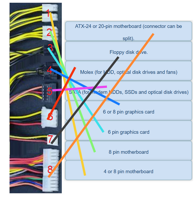
Screenshot from the contest host content
Why did I draw such conclusion if I'm to explain to a layman? First you need to observe the shape and size. You'll notice that it's kind of rectangular with two row of two pins and for the 8-pin, we have 2 rows of four pins. This is exactly what is shown here. The ability to split into two halves to accommodate 4 and 8 is What's unique about the connector.
| 1 | 8 |
|---|
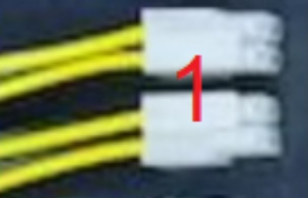 | 4 of 8-pin motherboard |
|---|
Concerning the wire colours, you'll notice that there are two yellow wires and two black in the 4-pin but as it has 8-pin too, we see 4 yellow wires and 4 black wires below. It is usually found near the CPU socket.
The role of this pin is that it helps to send voltage to the computer motherboard which helps to power the processor and other needed integrated circuit in other for the system to turn on. It sends electricity to the CPU as the brain of the system to function properly.
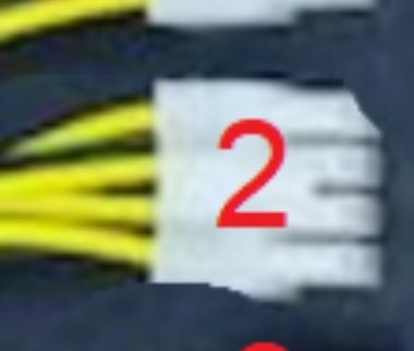 | 8-pin motherboard |
|---|
If you notice, we actually have 8-pin in number two which channels our attention to the 8-pin motherboard as it consists of four ground wires and four yellow wires with voltages of 12V. It is easily identified as this. It helps give additional power to the motherboard and power devices like the SATA ports and USB which needs high voltage to operate.
 | 6 pin graphics card |
|---|
The 6-pin graphic card connector supports picture or plug 3 which supplies additional power to the graphics card in a desktop. It helps send the needed voltages to the mounted graphics display card. From the picture below, we can outrightly see the connector has 6-pin arranged in rows of 3 and it's smaller than the 8-pin GPU connector.
It has 3 yellow wires and 3 black wires that acts as ground. It is seen from the PSU and connects to the graphics card. It needs extra power because more powerful GPUs need extra electricity to handle video editing and 3D aspects.
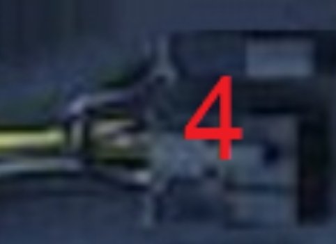 | 6 or 8 pin graphics card |
|---|
The 6 or 8 pin is also identified using the red and black wires but the distinct feature for finding this connector is that it also connects the power supply to the GPU and the pin differs from the later. It also need extra power to run the GPU effectively, generating less heat.
This type of connector connects or supplies 150W to the GPU to enhance its performance and also handle intense workloads. There's what we call overclocking which this connector supports. With sufficient power from the 8-pin connector, cooling attains stability.
 | SATA (for modern HDDs) |
|---|
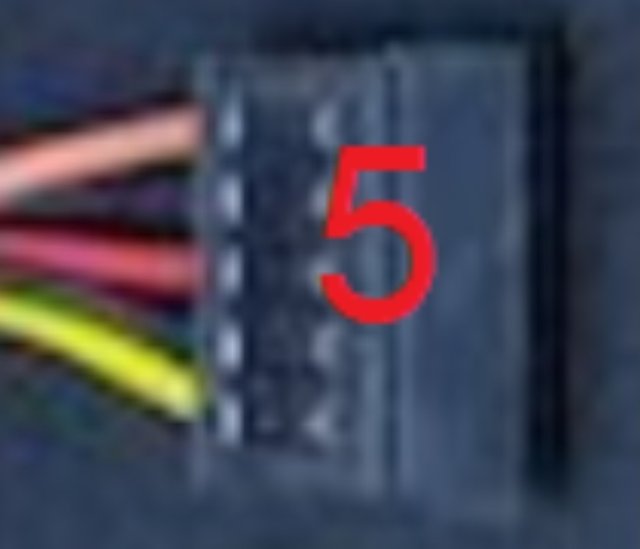
To identify a SATA connector, the physical features will help a lot. It is thin, flat and has an L-shape as shown in the picture below and it matches to number 5. It's very flat with not just two consistent colours. It has two connectors which are the data and power connectors with different numbers of pins. The SATA is majorly found in the motherboard, HDDs, etc.
It connects storage devices to the computer as its major role and ensure these storage devices receive power from the power supply unit as there's a discharge of power passing out of the unit through the DC connectors.
 | Molex (for HDD, optical disk) |
|---|
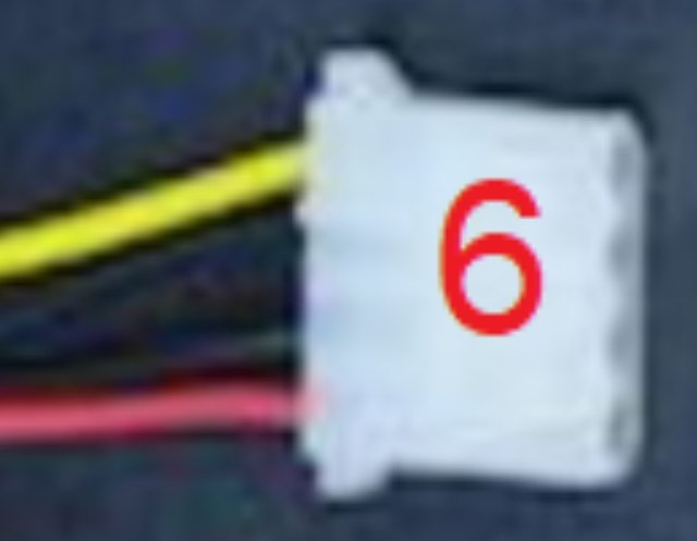
The molex for HDDs, optical disk drives and fans help supply power to the optical drives in older computers and is often used to power fans when they aren't enough fan headers, placed on the motherboard. It is also used to control fans and used in converting power to connectors like SATA through the support of an Adapter..It also helps send the needed voltage to this fan system to help cool this processing unit when the system is in use.
 | Floppy disk drive |
|---|
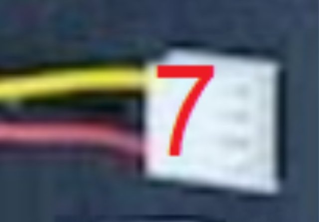
Floppy disk drive help boost old computers and installing software and also helps to power on the floppy drives for use when needed.
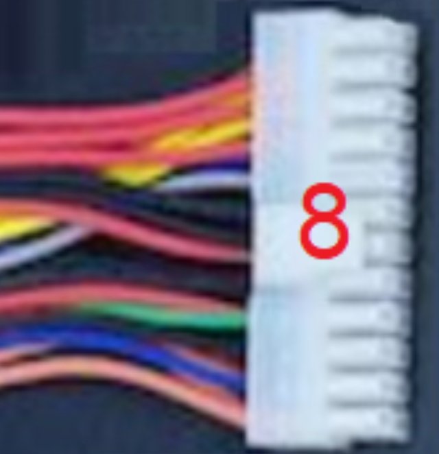 | ATX 20-pin motherboard |
|---|
The ATX 20-pin does a lot of functions due to the presence of those wires and their different voltages. It helps signal good power which protect the system's safety. It also provides power to graphics card, ensure the power supply unit provides stable voltage and also supply power to the RAM, CPU and USB ports. This particular connector connects the entire connector as the motherboard won't receive power without the Atx 20-pin .
There are various signs to show that your computer is failing. It may not be the reduced battery capacity alone but also other things like strange sounds, booting problems etc. It's similar in the case where your car throttles or the radio shut off randomly. These are signs to tell you the car battery is dying slowly. Same with a computer. The channel is the power supply if the voltage coming in is suitable for use by various components and the likes. A typical example is shown below.
- Your computer won't turn on even when you press the power button. No light beep or sound to show it's coming up. This is a common problem but can be diagnosed by checking the power outlet or cable outlet. You can use a different power outlet or change the power cable to see if its from there.
- Another sign is when you perceive burning sell. It could be that a wire or plug is affected. Unplug the computer immediately and repair it. You can actually uncoupled it to check which plug or wire develops this fault and ignoring this sign can be hazardous to the computer. Check the capacitors if they are swollen and other burn marks and repair immediately.
- The PC shuts down randomly and restart on it own without pushing the restart button. If this happens, check for overheating to see if the power supply unit is to hot and also check the fan if there are cobwebs around it as it can hinder the smooth running of the fan which could cause overheating. Checking the light source id very essential as unstable power supply can cause these shutdowns randomly.
Strange noise is another signal that a computer is faulty. Some people manages their cars even when the sound is abnormal. You'll hear a buzzing or clicking sound from the power supply which signals that the components of the computer may be failing and may damage other parts.
All of a sudden, the USB devices disconnects and fails to show storage devices. You can test the USB device of another computer to know the fault. You can also try using other ports as it's not just one port we have in a computer system. You will also notice screens that are dime. It's not normal. It's a sign of hazard you should be conscious of.
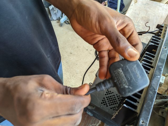
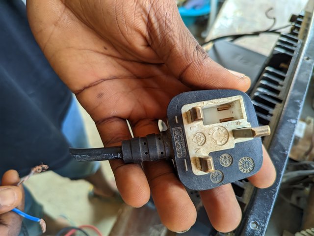
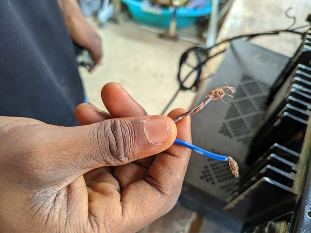
The use of the multimeter is to detect voltage supply and also check for bad sounds to identify faults. From the picture, I used a multimeter to test the plug as it refuses to power the system. I then came to find out that the problem was from the head which fails to send in signal to the computer to start. I hard to replace it by first of all cutting out the head and then testing the live and neutral wires to see if it reads on the multimeter and if the sound it produces is good.
 |  |
|---|---|
 | 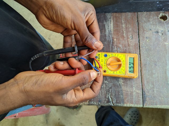 |
| Turn on your multimeter and place it in AC voltage | Place the two probs, the red and black |
|---|---|
| Place these two probs on the wire and check the voltage on the display | To check if it's still working, you place the multimeter in continuity and use your probs to check. |
| They'll be a sound produced after placing on both ends | Check the nature of the sound to detect this. |
There are a few precautions that must be taken when and cleaning a power supply. First, you must not remove the label on the post supply at any circumstances. It's boldly written there on the label not to be removed.

- Turn off power supply and disconnect from power source before cleaning or maintaining it to avoid electric shock. If not discharged properly, the stored energy can lead to electric shock which can cause death when maintaining it.
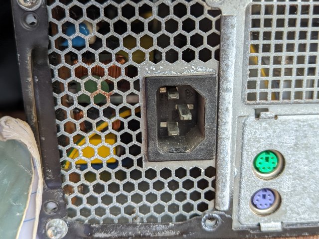 | Disconnect from power supply |
|---|
- The power supply ventilation should not be blocked. Whatever serves as hindrance to it should be removed to avoid overheating to ensure the smooth running of the PSU. Dust can cause overheating..
- Avoid touching high sensitive components inside the power supply as it could damage them and at no cost should you use water or any liquid to clean dust to avoid electric shock and short circuits. Instead of wiping as it may cause damage, the use of compressed Air can serve as a good tool for direct cleaning. Some people are used to wiping the components especially the fan areas of the power supply box.
- Always read the manufacturer's Manual before usage and ensure you use safety gloves and other safety equipment to avoid direct contact with electricity.
These are a few precautions one must take. They say a word id enough for the wise. I know everyone venturing in this field will have proper knowledge on safety..
In summary, the power supply acts as the brain of any electronic system and has connectors which ensures efficient power distribution to different components. It can function well if maintained and clean. So if you have a computer device, your power supply unit box channels energy throughout various components of the component. It is the backbone of the computer and a computer can't do without it just as your body can't do without your heart
This video above explains it all. This is the second content I made after mistakenly deleting the first one in the process of typing. Giving up wasn't an option.
Cc,
@kouba01
https://x.com/bossj23Mod/status/1892946803231781194?t=4-xyH40mV1kNEpXTdnylbg&s=19
Downvoting a post can decrease pending rewards and make it less visible. Common reasons:
Submit