As I already mentioned in the last post, I really enjoy taking things apart and figuring out how they work. And that is why I am going to start a new series of posts, in which I am going to tear down various electronic devices and document my findings for you.
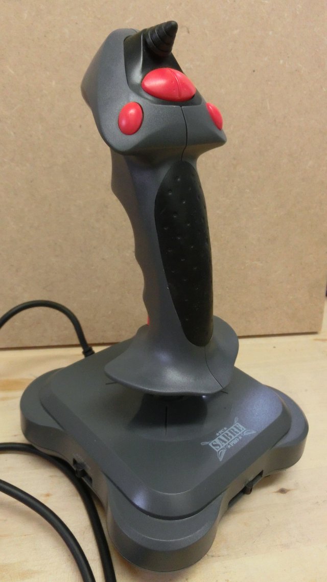
Some time ago I found this really old joystick in the attic of my grandparents and I took it with me to tear it down.
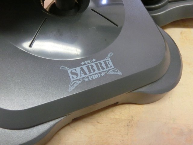
On the base of the joystick, there is a logo which reads “PC SABRE PRO” which from my point of view is a very general name for a joystick, but never mind.

The name of the product is further specified on the bottom of the base, apparently, the joystick was manufactured by a company called “INTER ACT”, and this specific model was called the “SV-214”. I think the internet has already forgotten about this company since I found no info about it.
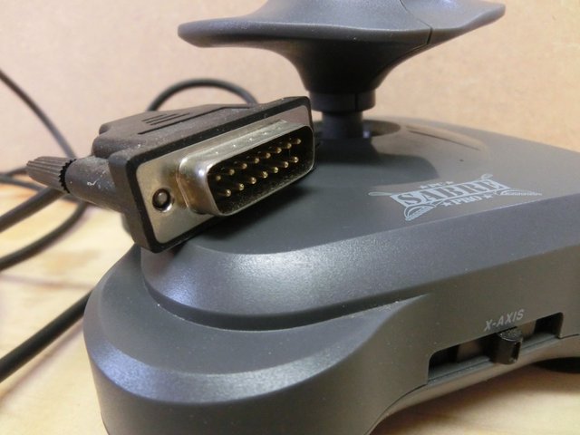
The joystick was connected to the pc via a Gameport connector, the traditional standard for joysticks and some MIDI devices. Sadly, I could never test if the joystick still worked, because my pc (obviously) has no Gameport connector.
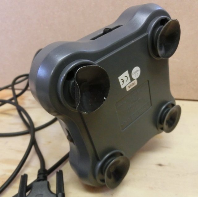
While gaming with the joystick it was held in place by four big vacuum cups.
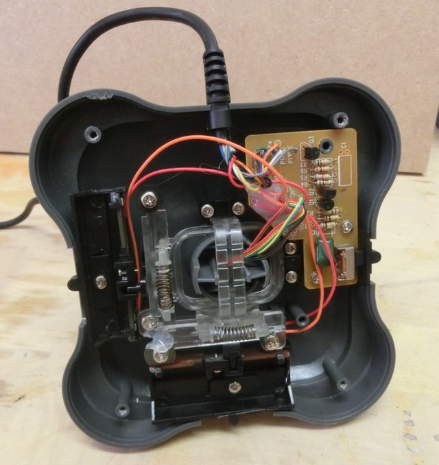
Inside the base, there weren’t as many parts as I expected, the mechanism for both axis and a small PCB with all the electronics.
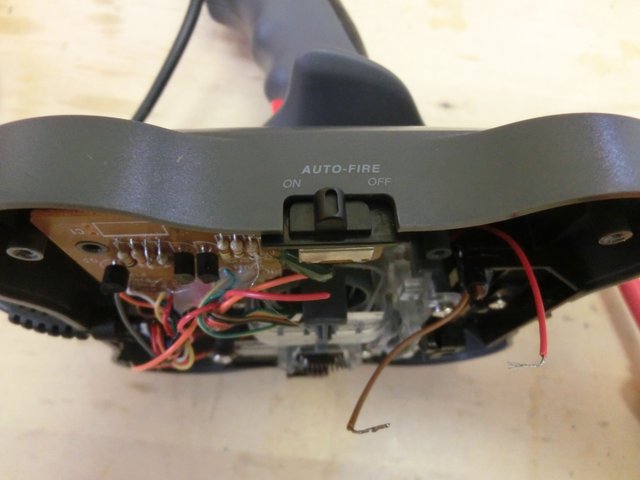
The only electric switch I could find was labeled “Auto-Fire”, and from my understanding, the only thing this switch does is that it repeatedly presses the fire button.
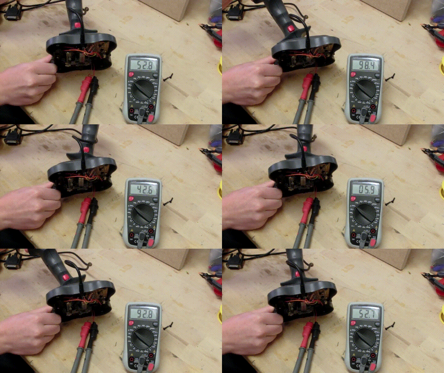
The Gameport natively supports X- and Y-axis inputs, that are controlled by adjustable 100k Resistors (Slide Potentiometers) which are connected to the plastic assembly that allows the joystick to move freely.
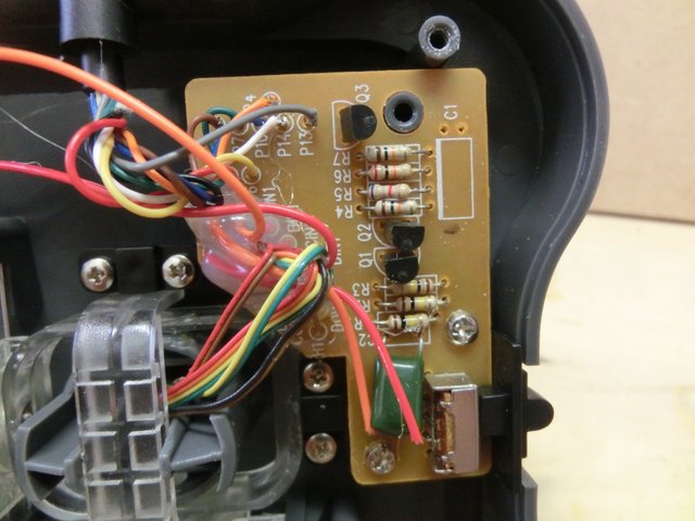
That is also the reason why there are only so few components on the PCB.
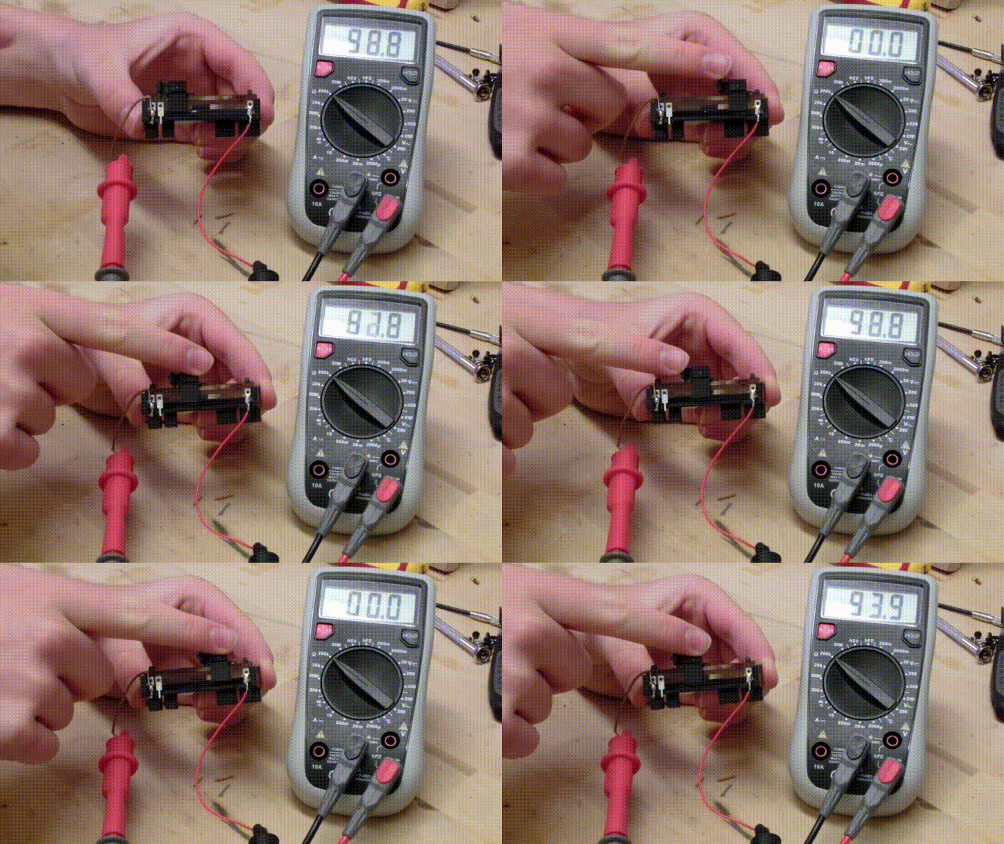
In order to better show you what is happening, I disassembled the resistor from the plastic assembly.
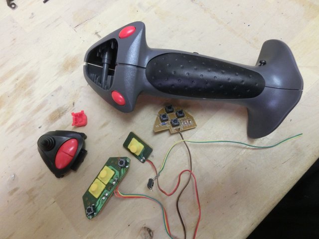
Inside the handle, there was a whole lot of nothing except for some buttons.
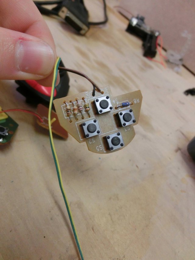
Four of the Buttons were mounted to a PCB to that only two wires were connected, and I was curious how they managed to trigger four different inputs with only two wires.
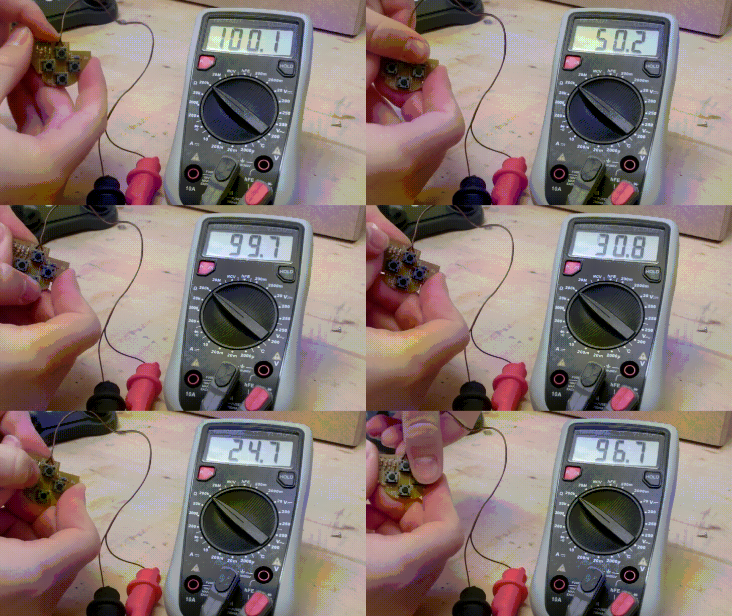
Every button is connected to a resistor, and by pressing the button you changed the resistance and one of the four inputs according to the resistance was triggered.
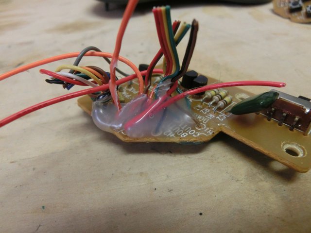
A professional strain relief in form of a big blob of hot glue was used to protect the solder joints.
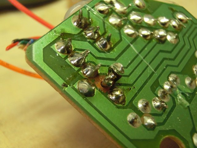
The great build quality of the PCB really impressed me (not).

Thanks for being interested in how an ancient joystick works and consider voting up if you liked this post.