Introduction
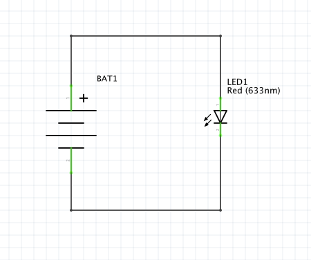
In electronics, circuit abstraction is used on top of Maxwell's equations for the common physic phenomena call "electromagnetic phenomena". The abstraction layer is also called "lumped circuit analysis". [1]
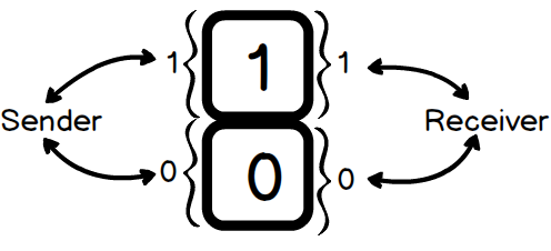
In this post, I would like to talk more about the digital abstraction. Digital circuit are a term used to explain devices that work in binary. Digital abstraction are dealing with voltage input and output (voltage are continuous) which are not ideally in zeroes and ones (digital signal are discrete). In order to solve this issue, it is quite common to do analog to digital conversion. How it works is that the analog signal will be map on the discrete digital level and convert it to digital signals. [2]
What is Digital?
- Digital are devices that work in binary.
- They are binary. Each binary can be either 1 or 0.
- Digital is an abstraction of the electric devices.
Why use Digital Circuits?
- It helps engineer focus on the digital behaviour of the circuit, ignore of analog and transient phenomena. Thus, it enables more complex circuit on top of small circuits.
- Helps logic designers to design complex digital circuits.
- Cheaper in terms of cost and function.
- Digital data can be compressed to reduce space and cost.
- Better noise immunity. Analog signal tend to lost energy while the data being transfer.
- Shorter time for development because it is easier to build a digital circuits.
Lumped Circuit Abstraction
| Physical view | Circuit Abstraction |
|---|---|
 | |
 | |
Lumped Circuit Abstraction
Voltage tresholds

Digital signal are send with an agreement between sender and receiver for the voltage levels and logical signals. With that, senders and receiver are able to communicate with each other.
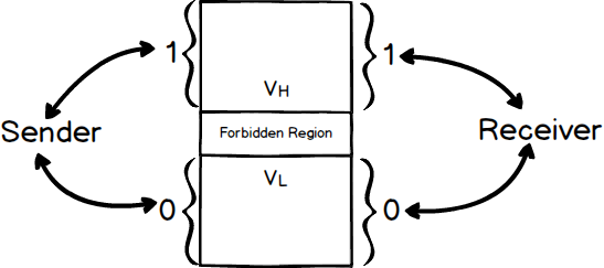
Forbidden Region

Forbidden region is introduced to eliminate the confusion of the voltage at the center between 1 and 0.
So when the forbidden region's voltage level is received, it will be undefined.
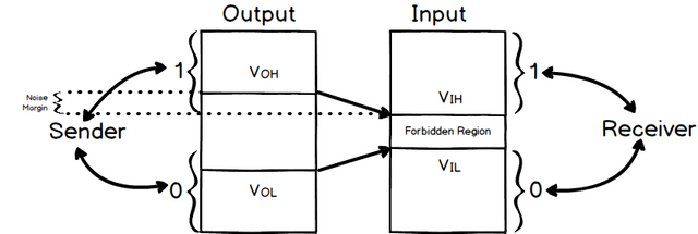
Noise Margin

Noise Margin is the absolute value of difference between the V0 (prescribed output voltage) and Vi (forbidden region voltage threshold).
Resources
[1] "Foundation of Analog and Digital Electronic Circuits", Anant A. et. al. 2005
[2] "Chapter 1: The digital abstraction" ( http://www.eng.tau.ac.il/~guy/Computer_Structure03/lecture_notes/chapter1.pdf )
This post has been curated by TeamMalaysia Community :-
To support the growth of TeamMalaysia Follow our upvotes by using steemauto.com and follow trail of @myach
Vote TeamMalaysia witness bitrocker2020 using this link vote for witness
Downvoting a post can decrease pending rewards and make it less visible. Common reasons:
Submit
Good info for sharing.. tq
Downvoting a post can decrease pending rewards and make it less visible. Common reasons:
Submit