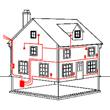
This is the first post on Electrical system this year 2018 and I will like to discuss on Electrical Installation Diagram of Building.

Installation Diagram:
This deals with the positioning of electrical component and appliances. A knowledge of building plans must have been acquired. The norms for a domestic building is that it must have:
   Living Rooms

   Bedrooms

   Toilet

   Bathroom

   Stores

   Kitchen

  Garage E.T.C
Take note of utilisation factor of each room which has to be specified. This will enable the Electrical Engineer to design:
  A. The level of illumination required for each room

  B. The type and quality of lighting equipment required

  C. Spacing of the lighting fittings for uniform illumination of each room.

  D. The type and quantity of power points required etc.
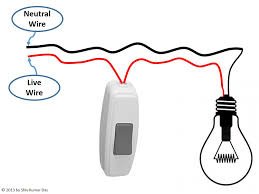
After all the calculation has been completed the positioning of each electrical point can be made on the plan of the building. The position of each lightning control must be made and a line is drawn to link each switch control to set lighting fittings it controls.
On the diagram the type of symbols used will specify the type of controls.

Electrical Draughtsmanship
This is a subject that deals with representation of electrical Installation and Distribution for a local community, machinery or factory.
To help easy representation certain symbols have been adopted in the electrical field to represent every electrical equipment.
If you are reading this short piece on electrical system it is assumed that we all have basic knowledge of Electrical Engineering technology. On this assumption it will be agreed that for a closed electrical circuit:
- Two electrical conductor will be required: (a) Positive and (b) Negative for single supply and are represented by two lines as follows:

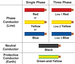
- Three or Four electrical conductors are required for a three phase supply as follows:

R = Red , Y = Yellow, B = Blue and N = Neutral. Three wires are used for the supply of 3 phase equipment, like Induction motors, where there is a balanced load and no Neutral line is needed.
There also in electrical drafting, it is common and easier to use a single line diagram for all supplies with identification notes on each line diagram used e.g.
In my next discussion I will shed light on Systematic and Wiring Diagrams.
Thanks for reading.
This topic is an interesting one. I like electrical draughting as a proper lit house is a delight to live in.
Downvoting a post can decrease pending rewards and make it less visible. Common reasons:
Submit
Thanks for your comment
Downvoting a post can decrease pending rewards and make it less visible. Common reasons:
Submit
I love this post but it's not advisable for non professional to practice it, it is for we professional's lol...
I can't wait to see your next post.
Downvoting a post can decrease pending rewards and make it less visible. Common reasons:
Submit
Congratulations! This post has been upvoted from the communal account, @minnowsupport, by samest from the Minnow Support Project. It's a witness project run by aggroed, ausbitbank, teamsteem, theprophet0, someguy123, neoxian, followbtcnews/crimsonclad, and netuoso. The goal is to help Steemit grow by supporting Minnows and creating a social network. Please find us in the Peace, Abundance, and Liberty Network (PALnet) Discord Channel. It's a completely public and open space to all members of the Steemit community who voluntarily choose to be there.
If you would like to delegate to the Minnow Support Project you can do so by clicking on the following links: 50SP, 100SP, 250SP, 500SP, 1000SP, 5000SP. Be sure to leave at least 50SP undelegated on your account.
Downvoting a post can decrease pending rewards and make it less visible. Common reasons:
Submit