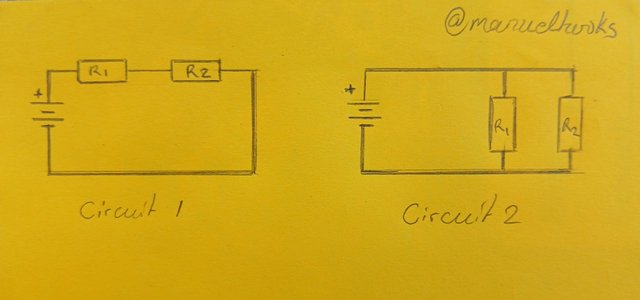
 Drawn and captured by manuelhooks and edited With Galaxy-A15
Introduction to Basic Electrical Circuits & Cable Joint.
Right from household appliances to industrial power systems, electrical circuits are now playing a critical role in our daily lives, it makes life comfortable and work easy and it has become the backbone of modern technology and development.
For this reason, our understanding of the fundamental concepts of electrical circuits is very essential for maintaining and creating efficient, reliable, and safe electrical systems
Workshop [Task A]
What is called an electrical circuit? Mention the importance of circuits in electrical engineering.
The closed path through which electric current flows is called an electrical circuit it is typically consisting of a power source like a battery or generator, some conductors in the form of wires or cables leading to a load which is the device to be powered, like a light bulb, motor. This setup will have to be controlled using switches, fuses, circuit breakers, and other digital means.
When I think of an electrical circuitry, I see a thrilling amusement park, where electrons ride the power wave as pulsating streams of charge. The electrifying journey unfolds in a loop, fueled by voltage to drive. driven by current and guided by wires, controlled by switches and fuses. All governed by fundamental principles like that of Kirchhoff's and Ohm's..
Basic Components of an Electrical Circuit
An electrical circuit relies on a cast of key players working together in harmony. Let me introduce the fundamental components of a circuit that makes it all happen:
1. Voltage Source (V) - Energy provider
2. Resistance (R) - Current controller
3. Current (I) - Electron flow
4. Inductance (L) - Magnetic energy storage
5. Capacitance (C) - Electrical charge holder
6. Switches - Current directors
7. Fuses - Overcurrent protectors
8. Circuit Breakers - Automatic safety interrupters
Why Circuits Matter:
Electrical circuits are the fundamental building blocks of modern electrical engineering, without circuits, we can't have electronics performing different tasks. they play a real crucial role in the design, development, and operation of electrical systems. Below are some of the importance of circuits in electrical engineering.
Power Distribution:
Circuits enable efficient and safe distribution of electrical power.
Electronic Devices:
Circuits are the backbone of electronic devices, from small smartphones to laptops and supercomputers, GPS, and other modern facilities.
Industrial Control:
Circuits control and monitor industrial processes, ensuring efficiency and reliability.
Communication Systems:
Circuits facilitate communication through telecommunication networks.
Energy Conversion:
Circuits convert electrical energy into various other forms like light in bulbs, heat in soldering irons, and motion in motors.
Safety and Protection:
Circuits protect people and equipment from electrical shock and damage.
Innovation:
Circuits enable innovative technologies, such as renewable energy systems and electric vehicles.
Workshop [Task B]
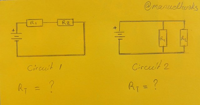 Circuits 1 and 2 are series and parallel circuits, respectively
Mention at least two differences between the series circuit and parallel circuit.
Note the above two circuits and mention their names, and calculate the total resistance of the two circuit. Assume any value of R1 and R2 but not the value specified in the course.
Series Circuit vs. Parallel Circuit
Series Circuit:
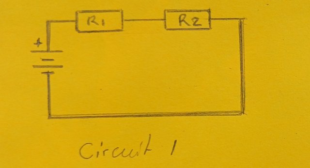 Circuit 1 is a series circuit
All components in a series circuit are connected end-to-end or head to tail. The head to tail connection allows current to flow through each component sequentially, passing R1, then R2 and so on. This setup allows the same current to flow through all components while the voltage is divided across components. The problem is, when one component fails, the entire circuit fails.
Parallel Circuit:
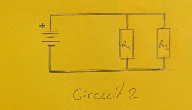 Circuit 2 is a parallel circuit
In a parallel circuit, all components gets connected between the same two points such that all heads are connecter in one spot and all tails together at another spot. The current in the circuit is divided across components while voltage remains constant across them all. Here, every component operates independently at such if one component fails, others continue operating with a slight disruption.
| Particulars | Series Circuit | Parallel Circuit |
|---|---|---|
| Wiring | Simple, less expensive | complex, expensive |
| Connection | End-to-end | Between same points |
| Current | Same through all | Divides across components |
| Voltage | Divides across | Constant all over |
| Component Failure | Entire circuit fails | Others continue operating |
| Reliability | Lower | Higher |
Calculating resistivity in series and parallel
Circuit 1 [series connection]
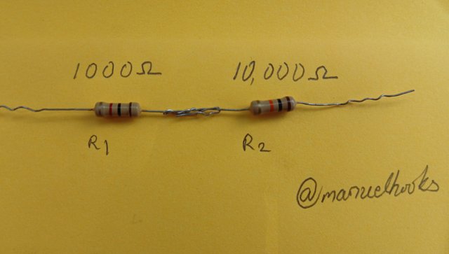
Assuming the values of R1 = 1000 and R2 = 10,000
Total Resistance in serise = 1000 + 10,000 = 11,000Ω
Total resistance = 11,000Ω
Circuit 2 [parallel connection]
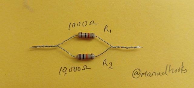
Assuming we are using the same values as above
R1 = 1000 and R2 = 10,000
Total Resistance in parallel
= 1/1000 +1/10000 = 0.0011Ω
Total resistance = 0.0011Ω
Observation, adding resistance in series increases the total resistance while adding resistance in paralel reduces the total resistance.
Workshop [Task C]
Take two pieces of wire and connect them properly. Be sure to mention consistent images and clear descriptions.
Here are the two wires to be attached. They are both single-stranded wires
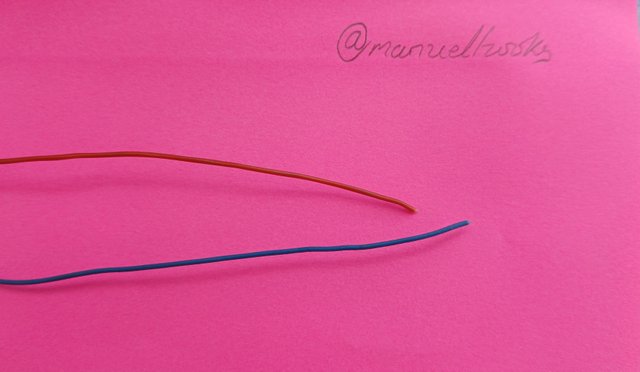
Now, I have to remove the insulation from the wires.
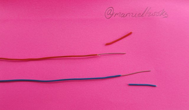
Make a 90° bend at half of the uninsulated end of the wire and hook both together.
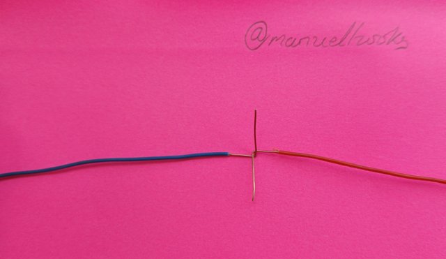
Hold firmly and twist one side around the other, the do the same for the other side.
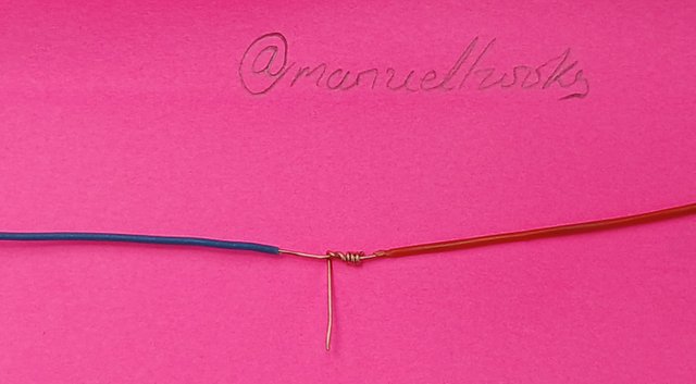
Finally, tighten both ends and use a multimeter set to continuity to get a loud buzz or full deflection.
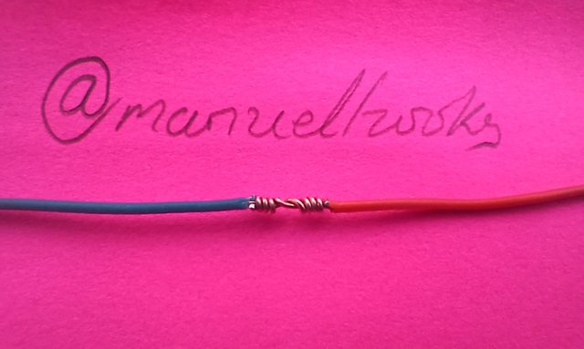
Crown it all up with an insulator to avoid accidental electrocution and short circuiting.
Workshop [Task D]
After completing this lesson write what you learn in your own words.
I have learned that simply adding two resistors together can produce very different outcomes depending on how the resistors were brought together. If the two values are being added in serise, the value goes up as a result of R1 + R2.
If on the other hand, the resistors are connected in parallel, the idea of following the parth of least resistance come in to play, and the total resistance is 1/R1 +1/R2 ....
Addition will not always lead to an increase
When connecting two cables, let the two cables tightly wrap on each other to make better contact.
Conclusion:
Thank you for the training and instructions, I will be open to corrections and suggestions from you all.
A very big thank you to the steemit team for the support and encouragement and for organizing this training. Thank you to my instructors, as I wish more of this could continue.
Invitation to contest
I am inviting @bossj23, @jozzie90, @josepha and @oasiskp this assignment requires no special tool, so let's make it happen.
#electricity-s21w2 #steemexclusive #nigeria #burnsteem25 #learnwithsteem
#electronics #club5050
https://x.com/manuelhook41759/status/1854106306333819076
Downvoting a post can decrease pending rewards and make it less visible. Common reasons:
Submit