Hello fellow steemians , a blessed Sunday to y'all, today I'll be participating on SLC22/WK5: Ladder Diagram PLC Programming and Solar Power by @mahadisalim
A |
|---|
What is meant by ladder diagram PLC programming? Draw a ladder diagram and explain.
A ladder diagram is a PLC program that converts electrical wiring into machine language wiring with the use of symbols to convert electrical wiring into ladder logics to enables it easier for electrical engineers to troubleshoot or program any automated systems
Example |
|---|
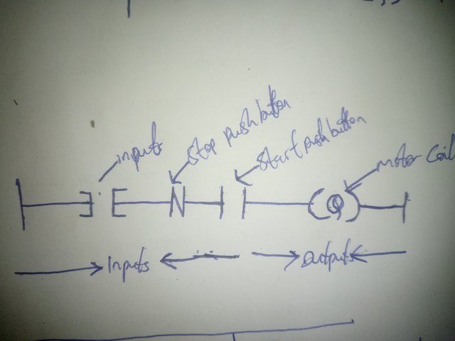
The above image is the ladder diagram of an electric circuit by me, you guys can all see that on the diagram symbols are converted to form ladder logic.
The first symbol from the left hand side is known as the Input and it's represented as (I) with the given symbols on the diagram, the second symbols on the diagram is the Stop push Button which is also referred to as Normal Close and it's represented as (NC) and it's used to stop pushing,the third symbols is the Start push Button it's as referred to as Normal Open and it's represented as NO it's used to start pushing. The last symbols on the diagram is the motor coil it's is the output and it's represented as (Q)
B |
|---|
Write the work by drawing the symbols of the input and output elements of the ladder diagram.
Inputs Element |
|---|
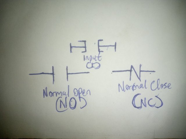
The above image shows the input elements of a ladder diagram which are the ,Normal open(NO),Normal close(NC) and the input (I)
Output Elements |
|---|
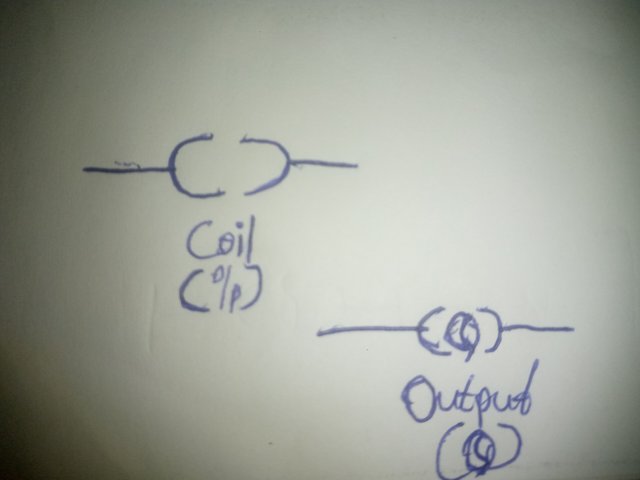
The above image shows the output elements of the ladder diagram which are the Coil (c) and the output(Q)
C |
|---|
Draw the ladder diagram with three input ladder logic gates (AND, OR) and explain with practicals.
AND Gates |
|---|
Materials
3 switches
Battery
Led light
|
|
AND ladder diagram |
| My practicals |
|
|
|
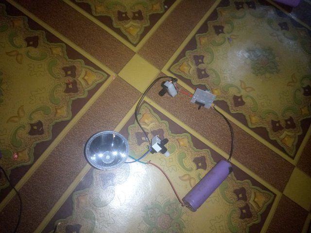
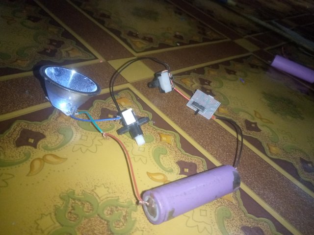
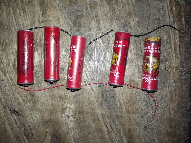
Practical using Led light with 3 switches and battery |
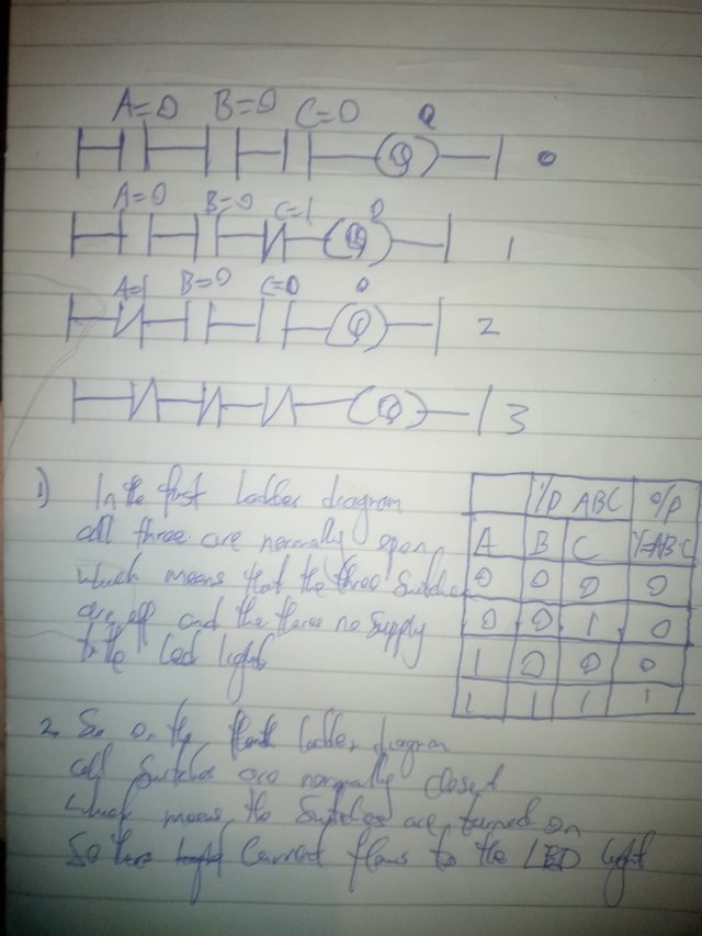
Tte above image shows the truth table, symbols and ladder diagram of an AND ladder logic gate with 3 inputs and 1 output ,tye three input are represented as A,B,C and the output gotten from the formula y= A.B.C
The truth tables A=0 and B= 1, and C=0 so output is Y = A.B.C Here, A=0 means NO (Normally Open), and B=1 means (Normally close) abd C=0 means (Normally open). We know NO means switch off. Since switches A and C are closed and then B is opened , the power supply to the output (LED light) is on.
OR Gates |
|---|
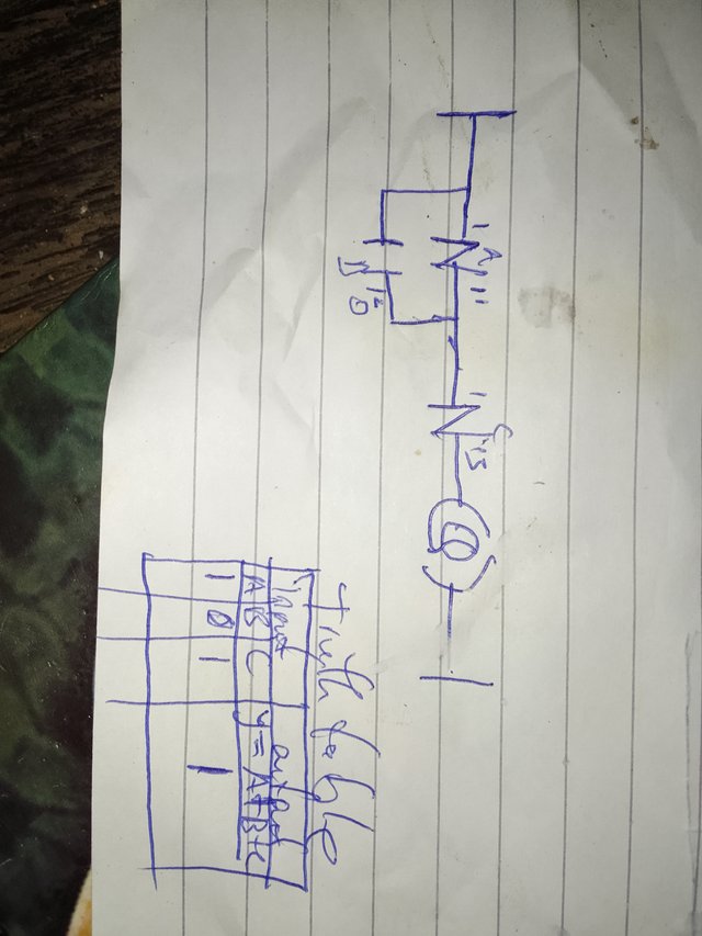
The above image show the truth table, symbol and ladder diagram of an OR ladder logic gate with 3 inputs and 1 output, the three input are represented as A,B,C and the output is gotten from the formula y =A.B.C
On the truth table A=1, B=0 and C=1 so the output Y=A.B.C here A =1 which is (Normally close), and B=0 which is Normally open then C=1 which is Normally close. The power supply to the output is on
D |
|---|
Convert the electrical wiring in the figure below into a ladder diagram.
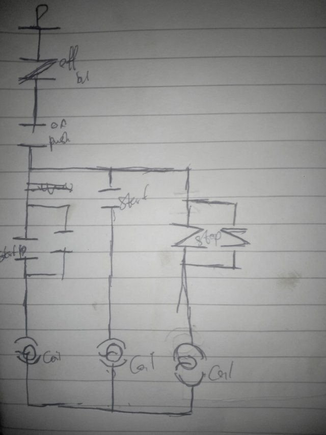
E |
|---|
Solar power is generated in your home with three 12-volt 100 AH batteries. An additional 12-volt 100 AH battery needs to be connected as your home's electrical load increases. Explain the series and parallel connection of four batteries with diagrams.
Series Connections |
|---|
Total voltage = V1 + V2 + V3 + V4
V = 12
= 12 + 12 + 12 + 12
Total Voltage = 48
Total Current = ?
Total Current = I1 = I2 = I3 = I4
100 = 100 = 100 = 100
Total Current = 100AH
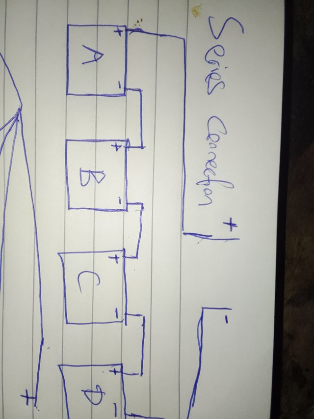
On the above diagram which is the Series Connections, the connection is done by connecting the negative head of the battery A to the positive head of the battery B then the negative head of Battery B to the Positive head of Battery C then the negative head of Battery C to the positive head of Battery D then the positive head of Battery A and the negative head of Battery will now stand as the main heads.
Parallel Connections |
|---|
Total Voltage = ?
Using Formula
Total Voltage = V1 = V2 = V3 = V4
Total Voltage = 12
Voltage remain same
Total Current = ?
Total Current = I1 + I2 + I3+ I4
= 100 + 100 + 100 + 100
Total Current = 400 AH
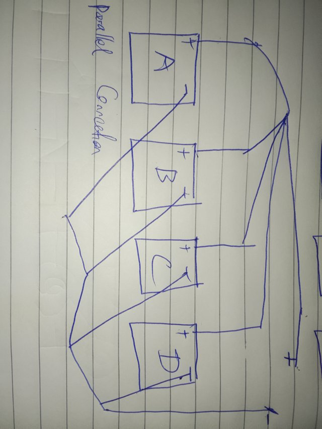
In the parallel connections the positive of the four batteries are connected to each other to form one positive head and also the negative of the four batteries are connected to each other to form one negative head
Series Connections |
|---|
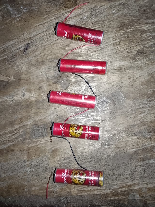
Parallel Connections |
|---|
Thank you sir for the wonderful class of the week I'll be inviting some of my steemit friends to join this wonderful lesson, @jozzie90,@samuelnkenta,@bossj23
