
designed with canva | • |
|---|
Being a Technician and also an Electrical and Electronics Engineering student, I feel that I'm even much more in a better position to give explanations on the Topic;
Also, with the knowledge that I have been able to aquire from professor @mahadisalim on the same topic. I will be able to answer the questions which are needed to be answered.
But first, let me just give a brief introduction about the transformer. Just Incase you didn't know.
Image of me showing a Distribution transformer | • |
|---|

Due to safety measures, an electric-wire fence has been put round the transformer area to avoid people or vandals from getting close...
What is a transformer | • |
|---|
A transformer is basically an electromagnetic device which converts voltage/current from high to low or vise versa without changing the frequency of the voltage.
We have two types depending on voltage;
1) The step-up
2) The step-down
But there are four main types depending on the use/function;
1) Power transformers
2) Distribution transformers
3) Instrument transformers
4) Auto transformers
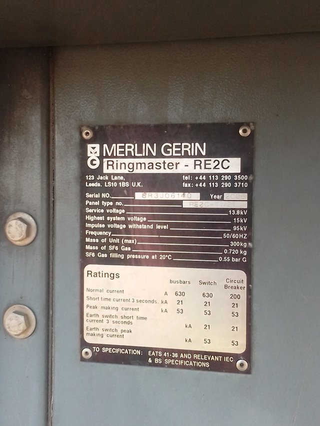 Specifications Specifications | Distribution transformer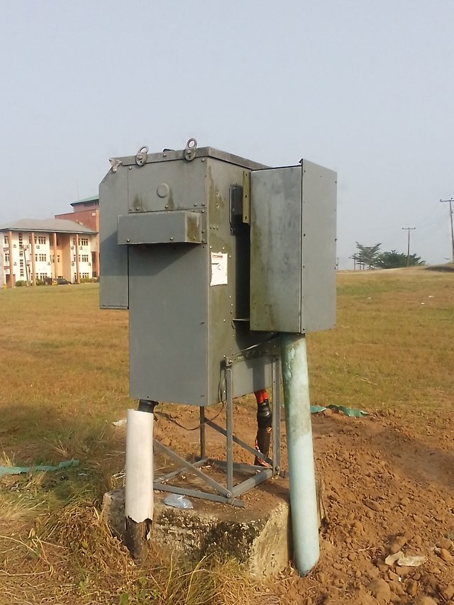 |
|---|
This one was actually covered, so I could go close enough to capture the specifications as well.
Now to the main course of this ;
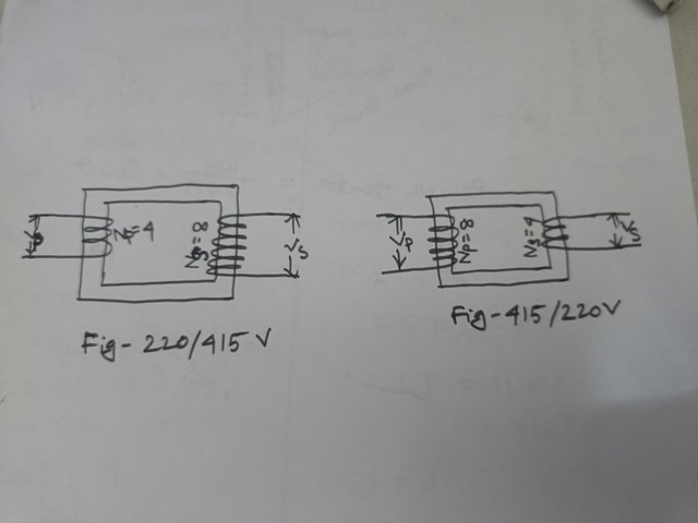
Name the two transformers from the diagram and explain why. | • |
|---|
Fig-220/415 v is a step-up transformer.
Why: Because , from the indication 220/415 v it shows that it's a step-up. Also , the voltage at the secondary side of the transformer is greater than that of the primary side. The number of turns too at the secondary is more than that of the primary side. All these indicates that the transformer is a step-up transformer.
Fig-415/220 v is a step- down transformer.
Why: Because, the voltage on the secondary side is less than that of the primary side.Also, we can see that the numbers of coil turns on the primary side is more than that of the secondary side. That is also why it has been indicated as a 415/220 v transformer.
What is the turn ratio of the two transformers | • |
|---|
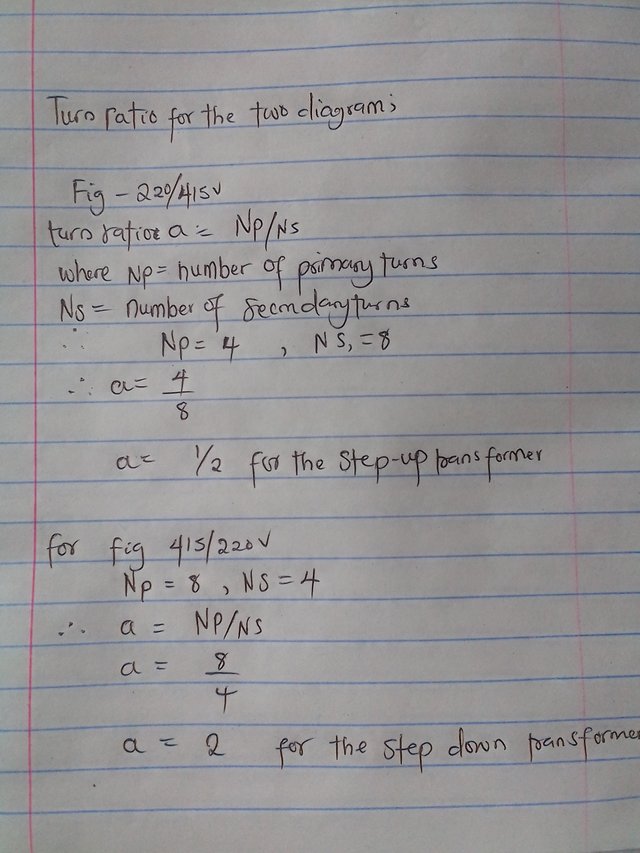
Turn ratio is the he ratio of primary turns to secondary turns of a transformer . And can be written mathematically as;
a = Np/Ns,
where,
a = turns ratio,
Np = number of primary turns,
Ns = number of secondary turns
Therefore, for Fig-220/415 v;
Where; Np = 4
Ns = 8
a = 4/8
a = 1/2 or 0.5
For fig - 415/220 v
Np = 8
Ns = 4
a = 8/4
a = 2
Therefore, the turn ratio for fig- 220/415 v and fig- 415/220 v are 0.5 and 2 respectively.
Identify the various parts of a power transformer with a picture and write the function of each part | • |
|---|
Labeled drawing of a transformer done by me.
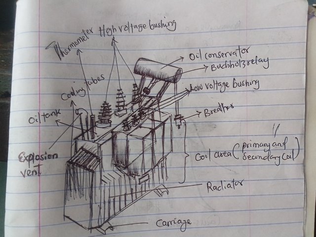 | . |
|---|
Core:
The core, which is also know as the coil area is the a basic part of the transformer. This where the magnetic core which the primary and secondary coils are located.
It acts as a low-resistance path for the magnetic flux which helps the winding to be coupled adequately. It also prevents interference as it confines the magnetic field within the transformer.
Bushings:
We have two types. The High Voltage bushings and the Low Voltage bushings
The high voltage bushings are usually bigger than the Low Voltage bushings.
Transformer bushings are electrical devices used in power transformer and other electrical equipment to provide insulation and support for the conductor wires that pass through the walls of the equipments.
They provide insulation for the conductors and also act as a barrier between the terminals and the tank. This helps to prevent voltage leakage and oil leakage into the conductors. They are essential in ensuring safe and efficient electricity flow.
Cooling Tubes:
Cooling tubes are also called cooling pipes. They are channels provided inside the design of the transformer which allows coolants, mainly oil, to circulate round the body of the transformer and ensure heat regulation. Thereby preventing damage due to overheating.
Transformer Tank
The transformer tank is a container that serves as a houses for all the essential components of the transformer. Essential component s like core, windings, insulation, cooling systems, amongst other requires protection from external factors that may cause damage to the transformer if they are being tampered with. So, the tank helps in covering
Breather:
A breather is also called the silica gel breather. It is used in power transformers to control the quality and quantity of air that enters or leaves the shell of the transformer. The main function is to prevent moisture and dust from entering the transformer. Ensuring a dry and contaminant free air in the transformer.
Explosion Vent:
Explosion vents are metallic pipe positioned just above the conservator tank. It is a specific type of pressure relief device used in transformers to mitigate the risks associated with explosions.
Fir Incase of explosion, the vent helps to divert pressure away from important parts of the transformer. It also help to release pressure and gases during explosion or pressure build up.
Oil Tank:
The oil tank is container which holds the transformer oil, such as mineral oil, pyrsnol, silicone oil. These tanks are typically constructed from robust materials like steel to provide both structural integrity and the ability to endure the mechanical and thermal challenges that comes with the operation of transformers.
The oil tank is to store and contain the transformer oil. It holds an amount of oil that is enough to ensure proper cooling and insulation of the transformer during its operation.
Buchholz Relay:
The Buchholz relay is a very important components in the transformer. It is usually incorporated in oil-immersed transformers that's rated over 500kVA. The Buchholz Relay is a protective device used to detect faults and abnormalities within the transformer.
Oil conservator:
The oil conservator is an expansion tank that is being connected to the transformer’s oil tank, accommodating oil volume changes due to changes in temperature. It is usually place above other parts of the transformer.
The oil conservaTor ensures a stability in oil level within the transformer. It achieves this by accommodating oil volume changes resulting from temperature fluctuations which may cause a contraction or expansion in the main tank.
The Radiator:
The radiator is a series of fins or tubes attached to the exterior of the transformer casing. These fins or tubes are usually made of copper or aluminum which are good conductors of heat. The radiator works by providing a larger surface area for heat exchange, allowing heat generated by the transformer to be transferred to the surrounding air more effectively.
Transformers operate at high temperatures and the radiator helps to keep the transformer cool by transferring heat away from the internal components.
Thermometer:
The thermometer in a power transformer may be a simple dial or digital device mounted on the transformer casing. It contains a temperature sensor or in most cases a thermostat that is connected to the internal components of the transformer to measure the temperature. Some transformers may have multiple thermometers at different locations throughout the transformer to monitor temperature variations.
The thermometer allows operators to take appropriate actions if the temperature exceeds the safe limits, such as adjusting the load or cooling system.
What type of transformer is used for your home's electricity? Describe your understanding with pictures. | • |
|---|
We use the Distribution transformers for our home's electricity.
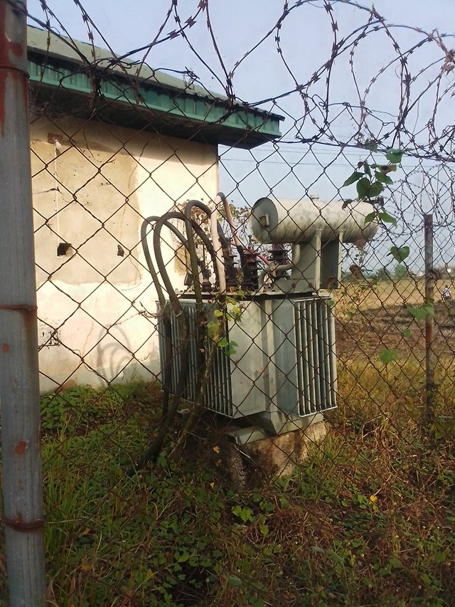
These are the ratings;
Input Voltage: 415V(3 phases)
Output Voltage: 220V to 240V
Power Rating: 5 kVA, 10 kVA, 20 kVA, or higher (depending on the power requirements of the application)
- Frequency: 50/60Hz (standard frequency in Nigeria)
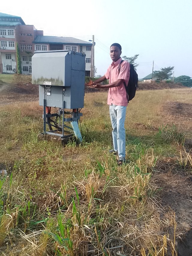
These transformers are designed to step down the three-phase high voltage supply to a lower and more manageable voltage level for home use.
Note, transformer ratings and configurations can vary depending on the specific application and requirements.
Calculate how many KVA transformers will be required for a 5000 KW load. | • |
|---|
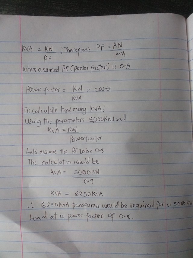
KVA = KW/ PF
Therefore; PF = KW/ KVA
Where assumed PF ( Power Factor) is 0.8
Power Factor = KW/KVA = cos ¢
We calculate how many KVA;
Using the parameters 5000KW Load
KVA = KW/ Power Factor
With the assume PF of 0.8
We calculate;
KVA = 5000/0.8
KVA = 6250
Therefore, 6250 KVA transformer would be required for a 5000KW load at a power factor of 0.8.
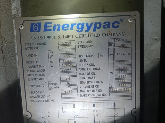
Look at the transformer's nameplate in the picture and find out the following points. | • |
|---|
Transformer Name: Step-down/ Distribution transformer (IEC-60076)
Transformer Rating = 2500 KVA
Primary Voltage(HV) = 33KV
Secondary Voltage (LV) =0.415KV
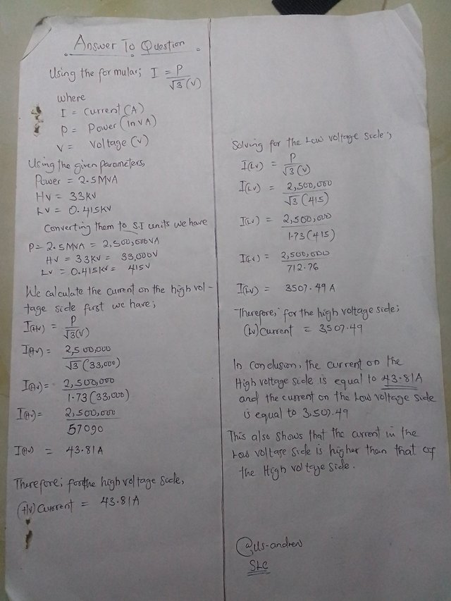
Current (HV) = 43.74 A
Current ( LV) = 3478.11 A
Find the currents in the high voltage (HV) and low voltage (LV) sides of the 33/0.415 kV, 2.5 MVA transformer. | • |
|---|
What do you mean by power factor? What is the power factor value given by the electricity supply company in your country? | • |
|---|
From our previous calculations, we were able to derive that Power Factor (PF) can be written mathematically as;
PF = KW/KVA
The power factor actually denotes how much electricity we consume. It is the ratio of active power to apparent power. It can also be the cosine of voltage and current.
The power factor is very important in industrial electrical engineering . Normally, it has an ideal value 1.
It doesn't have a unit.
In my country Nigeria, the power factor value given by the electricity supply company is typical between the range of 0.8 to 0.9. Which indicates some inefficiency in the system. And this causes wastage of the electricity supply. By Improving the power factor in our country , it can help increase the efficiency of electricity usage and reduce energy waste in that country.
Given the nameplates of the two transformers shown in the figure, write three differences. | • |
|---|
| A | B |
|---|---|
.jpeg) | .jpeg) |
Differences | • |
|---|
| Specifications | A | B |
|---|---|---|
| Ratings in KVA | 2500 | 200 |
| Input(HV) | 33KV | 11KV |
| % Impedance | 6.6% | 4.07% |
From the differences, we can tell that transformer A is a bigger transformer compared to transformer B.
Please, next time when taking the pictures, go close enough ,so we can see the specifications clearly. It was so tiring trying to strain my eyes to see well. Talking specifically about the B-side. Thank you.
Determine True/False: | • |
|---|
The name of the oil used in a transformer is pyranol.
Answer: TRUE
Commercial name
The core loss of the transformer is in the winding.
Answer: FALSE
The efficiency of the transformer is less than that of other electrical devices.
Answer; FALSE
The transformer rating is in KW.
Answer: FALSE
The transformer's insulation test is done with a megger meter.
Answer: TRUE
Cc @mahadisalim
I'll like to invite @bossj23 @imohmitch and @promisezella to participate.
Please use this link ;
https://steemit.com/steemexclusive/@mahadisalim/slc22-wk1-advanced-electrical-transformers-and-the-power-factor
This is absolutely impressive
Downvoting a post can decrease pending rewards and make it less visible. Common reasons:
Submit
Twitter promotion link;
https://twitter.com/bobby_andrew01/status/1869878625430057063?t=KdkOOTLCHnG0wyztKt9Z5w&s=19
Downvoting a post can decrease pending rewards and make it less visible. Common reasons:
Submit