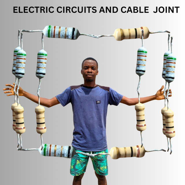
Edited using canva
Imagine walking into a dark room, and you turn on the light. The whole room that was dark is now filled with light. This action is as a result of connections in a network that are wired, called an electric circuit. If you notice, rechargeable lamps, torches, and charger heads have circuits inside them that allow current to pass through.
At first I usually think it was a motherboard or small transformer, not knowing it's a circuit consisting of resistors, connected wires, etc. From my description, you should have pictured the circuit in your eyes already.
What is called an electrical circuit? Mention the importance of circuits in electrical engineering. |
|---|
An electrical circuit is a closed part that allows the flow of electric current with components like resistors, capacitors, inductors, and power supplies. These components all have roles to play in the working of an electrical circuit. In a circuit, there's presence of Voltage, current passes through and resistors controlling the inflow of current.
An electrical circuit is just like a road system that allows cars to travel on it. **Power source pushes the current, wires carry the current, and the load uses the current, all as a result of the electric circuit.
An electrical circuit is especially a closed path through which current flows. In an electric circuit, the current will return to the power source from which the current flows through. In the case of current flow, it flows through different paths. In a series circuit, there is one path of current flowing and in parallel circuit there are multiple paths of current flow which doesn't read same current.
The electrical circuit requirements are the power source, components, Load management, voltage and current distribution, power measurement etc.
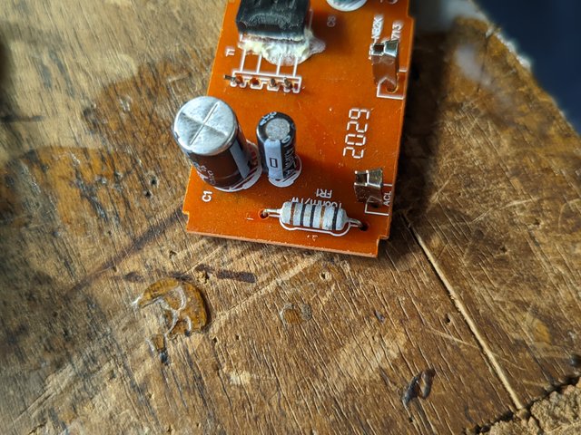
For electricity to flow, which passes current, the circuit must be closed or complete in such a way that it is captured. The circuit serves as a regulator that prevents direct current from just passing through the load. When current passes through a circuit, resistors control the flow of electrical current and convert some of the current to heat.
The benefits of electrical circuits in the engineering field are that, as a circuit, it has roles to play in making light and life seen in electrical appliances and direct connections in homes. Electrical circuits are useful in
Powering devices and systems since it does the work of controlling the inflow of current.
Communication systems and mobile devices Even laptops and televisions need an electric circuit to function or work, as it is designed to control the flow of current passing through it.
- It Can also be useful in transportation systems, industries that use heavy machines, and household electronics. In transportation, it can be related to aeroplanes and train systems. These are some of the advantages of electric circuit in these areas. It's just like the heart of an electrical appliance. Without it, the functionality is not seen or heard.
Mention at least two differences between series circuit and parallel circuit. |
|---|
There are two types of circuits, which are outlined in the contest post: series and parallel. These two circuits work differently with their unique properties as current flows through them. In a series circuit, the components of the circuits are connected end-to-end in a straight line, which means that the current flowing through that circuit is the same because the components are on a straight line.
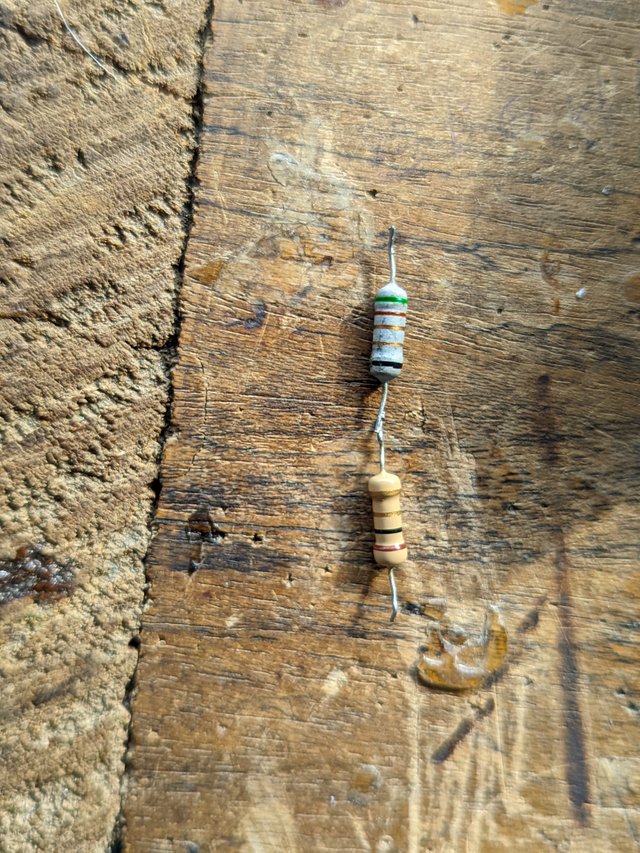
Each of these components depends on the other to function; that's why, when removed or disconnected, if it's a bulb, the other bulb would be affected. It is called a series circuit because the components are arranged in sequence and the same current passes through them.
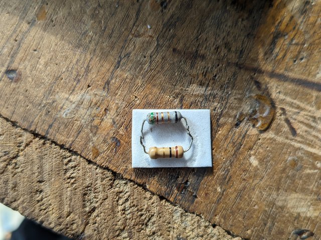
In a parallel circuit, the same current doesn't pass through or flow in its components because they are not arranged sequentially but opposite each other. They don't depend on one to function even when disconnected. Same voltage passes through its components, but the same current doesn't become there's a division in the flow of current. Talking about the differences, I'll say:
| Category | Series | Parallel |
|---|---|---|
| Pathway Flow of current | There's only one pathway for the flow of current as components are arranged in a single line | There are multiple paths for current to flow, and the components are independently functional. |
| Behaviour of current flow | Same current flows in series circuit components as there's no division and it remains constant throughout the circuit | Different current flows as there's a division in the path of these components. They have different amounts of current flowing through them. |
| Voltage | The voltage is divided by the total number of components to determine the total voltage in the circuit | Each component in the circuit receives the full voltage of the source of power, and there's no division singly. |
| Break in circuit | Affected | Unaffected |
| Total resistance | Is the sum of all the components's resistance | is the inverse of the total resistance in a circuit. |
Series circuits are practically used in simple applications like Christmas lights. If one bulb fails in this circuit, the whole bulb is affected. Parallel circuits are used in household wiring. If one bulb malfunctions, it doesn't cut off the light from other bulbs.
Note the above two circuits and mention their names, and calculate the total resistance of the two circuit. Assume any value of R1 and R2 but not the value specified in the course. |
|---|
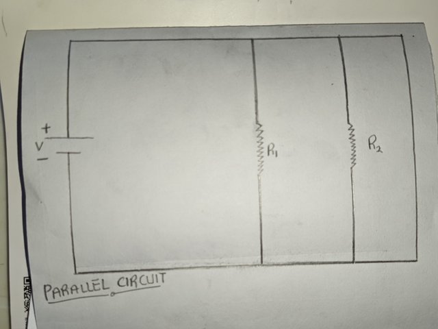
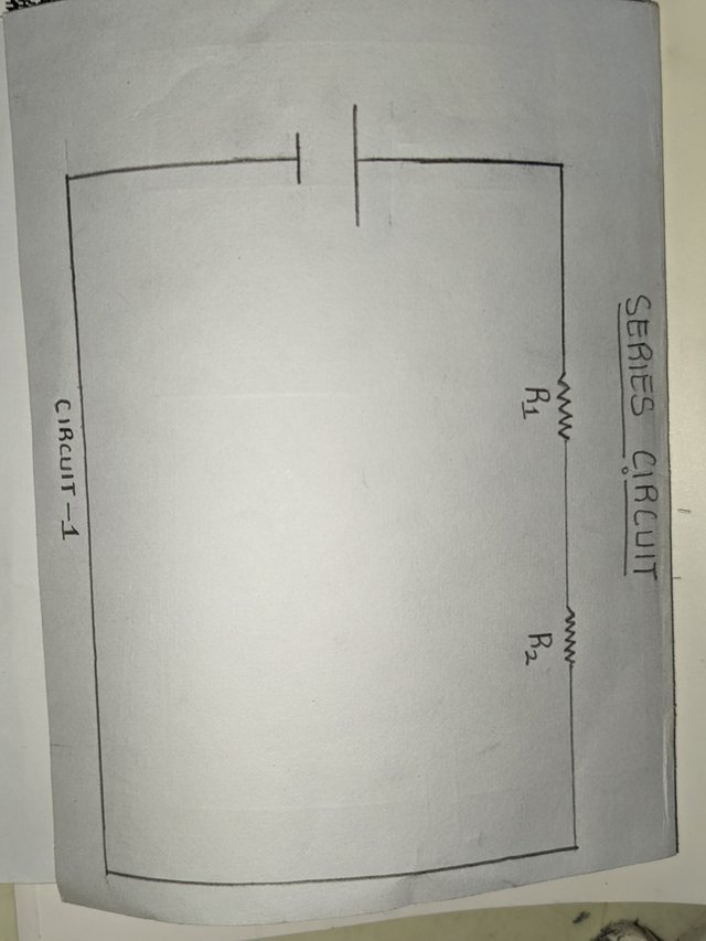
The first circuit that has resistors on a straight line is called a series circuit because its resistors are on a straight line. The same current passes through it. While the second picture is a parallel circuit showing that different current passes through them by their positioning. They are across each other and behave independently. To calculate the total resistance in these two series, the video will make a clear explanation of this. Let's start with the series circuit.
 |  |
|---|
Our assumed values are:
R1 - 100 ohms
R2 - 200 ohms
Series circuit.
We have our two resistors. To find the total resistance Rt, we get the sum total of each component in the circuit, which is R1 + R2....
Rt = R1 + R2
Rt = 100 + 200 ohms
Rt = 300 ohms
We got the total resistance in this series circuit by adding the two components to get the total resistance. Rt = 300 ohms
Parallel
We do the inverse of the sum. 1/Rt = 1/R1 + 1/R2.....+ 1/Rn. Having our values as 100 and 200 respectively, we have it that
1/Rt = 1/100 + 1/200
1/Rt = 2+1/200
1/Rt = 3/200
3Rt = 200(1)
3Rt/3 = 200/3
Rt = 66.67 ohms
Take two pieces of wire and connect them properly. Be sure to mention consistent images and clear descriptions. |
|---|
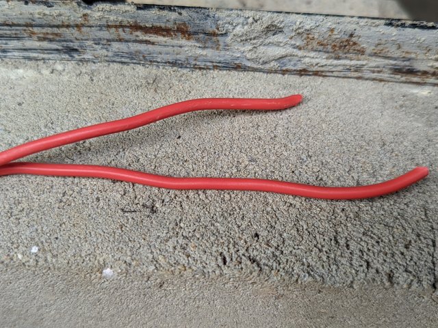
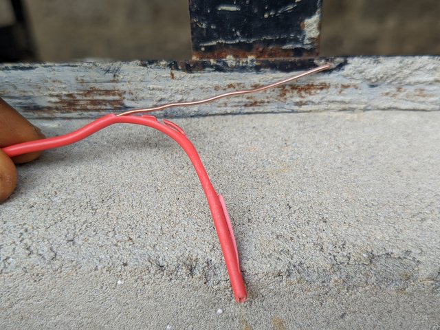
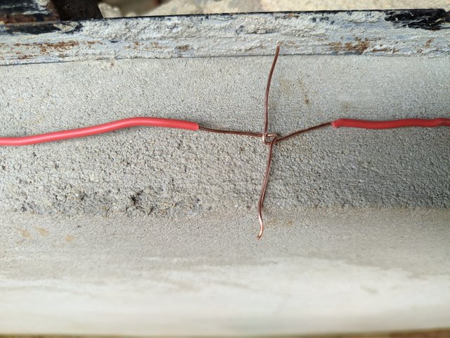
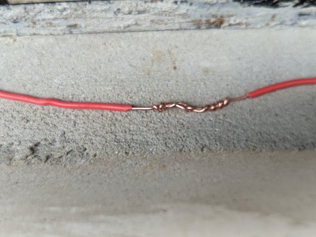
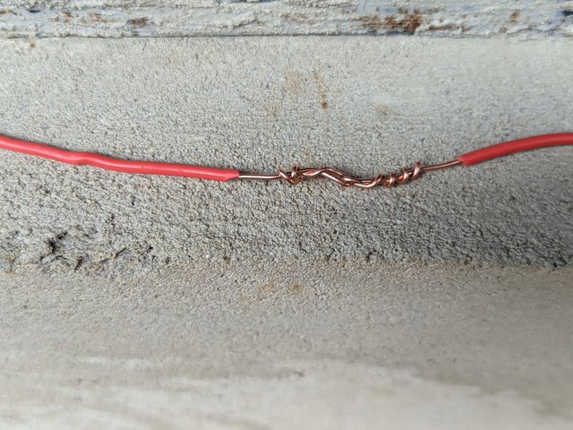
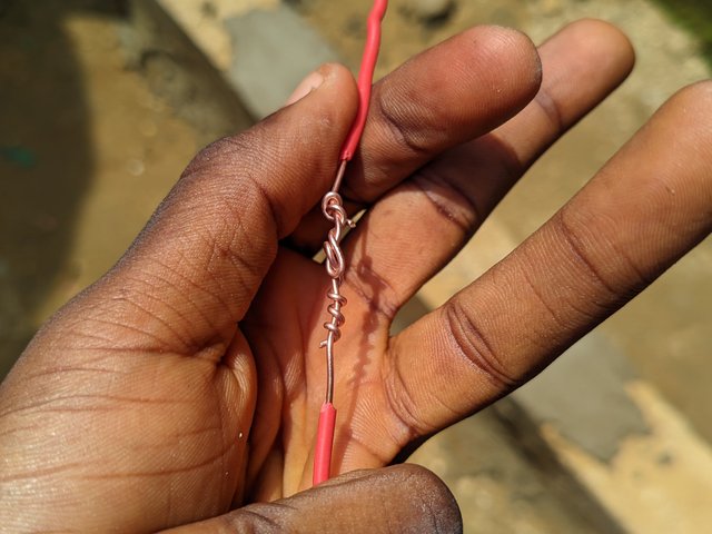
I have with me two pieces of copper wire, and I did join it by using a sharp knife to cut off the coat from the wire to get the copper metal visible. Having made these two pieces naked, I took to joining them by first intersecting them on both pieces and then using the intersection of one to coat the other while the other coats the one opposite it. That's how I was able to connect the wires properly to avoid exposure and any form of electrical shock.
 |  |  |
|---|---|---|
 |  |  |
After completing this lesson write what you learn in your own words.
I learnt what electric circuits are and how it being closed or complete helps in the functionality of most gadgets and appliances we use today. I learnt that same voltage passes through a parallel circuit and same current passes through a series circuits. I also learnt that in series connection, if one component is bad, the other would be affected whereas it's not the case with parallel circuit.
The total resistance in a series circuit is the total number of components while that of a parallel circuit is the inverse sum of the components. I also show how this electrical circuit can be applied in real life asides electrical engineering.
I invite @ahsansharif, @irawandedy and @walitcd
This is very great and educative..,
I will love learn more and also practice it
Downvoting a post can decrease pending rewards and make it less visible. Common reasons:
Submit
Wow am so excited for this post I can see you are Illustrating to us on how electrical circuits & cable joint works, which is necessary for human life
Downvoting a post can decrease pending rewards and make it less visible. Common reasons:
Submit
Taught like the educationist that you are.
Well explained, bravo!!!
Downvoting a post can decrease pending rewards and make it less visible. Common reasons:
Submit
A top notch presentation,mere going through this I can say I have a fair knowledge on basic electrical circuits.Really nice work done here by you
Downvoting a post can decrease pending rewards and make it less visible. Common reasons:
Submit