Today is another beautiful day with the electrical lessons. Greetings to you all, and welcome to my blog! Today is about PLC, what it does and what it is all about.
[A.] What do you understand by industrial automation?
Instead of using the traditional manual method of running things, which is less efficient, going for a more efficient method that involves the use of automated processes made possible by applying both technology and machinery to control industrial and manufacturing processes.
Industrial automation refers to a system where there is a reduced intervention from humans such that machines are doing the work previously done by humans in the production process.
The human intervention in the process is replaced by sensors and actuators that communicates with a control system responsible for decision-making and robotics or mechatronics that carry out the decision. Such a system may also be upgraded with a feedback communication network and some kind of artificial intelligence that allows the system to learn and evolve.
[B.] Write about the importance of industrial automation during the Industrial Revolution.
No matter how hard you and I may try, we as humans have a limit to how far we can go and how well we can perform any given task. We get tired, exhausted, and fatigue often sets in. Machines do not get tired and do not have our weaknesses.
Automation has a higher level of efficiency. More work can be done in relatively less time while maintaining quality and speed, it also reduces wastage.
Another advantage of an automated system is its low cost when compared to managing people and their antics. You will not need a human relations manager or pay for overtime, accidents, and calls for a pay rise, overtime, or a lawsuit over abuse or working conditions.
The machines will not wake up one day and make demands or engage in strike action or join in a sympathy strike organised by labour.
[C.] Write the names and operations of various parts of a PLC with a picture.

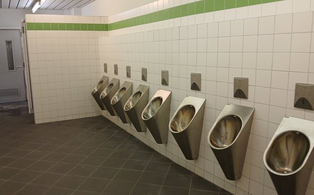
To keep this restroom clean and hygienic, water is used to flush it.
Traditionally, the flushing was done manually or at the press of a button. Today, programmable logic controllers running automated cleaning systems are taking care of public toilets like this one.
The small box on the wall will see you coming and will stop flashing when it see you walk away.
Input/Output terminals
Mostly made up of sensors, the I/O cards connect your PLC unit to other devices in your facility, functioning as the eyes and ears of the system. The sensors can tell when someone is standing at the urinal and when someone has just used the toilet.
This information is then transmitted to the processor.
Communication networks
The programmable logic controller has a communication network that interconnects its different parts, allowing the sensed signal to be sent to the processing unit, and the resulting decisions are communicated to effectors.
The processing component
The main processor is responsible for examining the signals it obtained from the sensors and to come up with a response to it. Based on the input signal, the processor generates a response and communicates it to the effectors, which opens some valves and allows water to run, flushing the toilets.
Power Supply
These devices are often classified among output components of the PLC. These are devices attached to control valves, motors, servos, release switches, and monitoring systems.
Effectors
These devices are often classified among output conponents of the PLC. This are devices attached to control valves, motor, servos, release switches and monitoring systems.
[D.] Name five input and output electrical and electronics devices operated by PLC.
Inputs:
Proximity Sensor:
A proximity sensor, like either the one used in a car or an assembly processing line, helps to detect the presence or absence of an object and sends a signal telling its location and proximity to the PLC. The PLC will then make use this signal to trigger an action; such as turning on or off a motor or activating a valve.
Limit Switch:
A limit switch is a mechanical switch that functions like an eye. It is activated when an object gets to a certain position. The PLC can use the signal from the limit switch in controlling the movement of a machine or device.
Photoelectric Sensor:
Photoelectric sensor are able to detects changes in light intensity and will sends a signal to the PLC. It could be used as a counter telling how many objects have walked passed a specific point in an assembly line. The PLC makes use of this signal to trigger an action, turn on a light, or activate a conveyor belt to start moving.
Temperature Sensor:
This are sensors that can detect an measure the temperature of a component, product or device. and will sends a corresponding signal to the PLC. This can protect against overheating or even tell when the next movement is due. The PLC can use this signal to control the temperature, such as turning on a heater or cooler.
Pressure Sensor:
Pressure sensor are often mounted inside tanks to measures the pressure in a container and sends a signal to the PLC. Some cars can tell when their tires are getting deflected or when a gas tank is full. PLC can use this signal to control the pressure, such as turning on a pump or valve.
Outputs:
Motor Starter:
Based on the received signal, a motor could be stated to effect movement or made to stop working. A conveyor on a production line is a good example.
Valve Actuator:
As I observed in a washing machine, a valve actuator is an electrical device that can open or close a valve based on what signal it receives from the processor. The PLC processor can send a signal to the valve actuator to control the flow of incoming fluids or gases.
Lighting Control:
A lighting control system can be operated by a PLC to turn lights on or off, or to adjust their brightness.
Heating/Cooling Control:
Temperature control can be automated so thet when the temperature gets to a critical point it triggers a cooling system. In my laptop the fan will run faster till the temperature is brought down.such control system are operated by a PLC's processor who provide the fan the signal to run.
Alarm System:
When the situation is critical and would need humans intervention, an alarm system can be activated by the processor, calling the operators or maintenance personnel of abnormal conditions or faults in the system.
[E.] Practical:
The power load for setting up an industry is assumed to be 10 MW. Five 5 kW and three 45 kW three-phase motors will be used in the production of the product. You are an electrician or electrical engineer in that company. Perform the following electrical works with responsibility:
The incoming electrical line in the industrial area is 11 KV. Prepare a transformer specification by first calculating the load.
To calculate the load, the following variables will be needed:
| Type and number of equipment |
| Equipment ratings |
| Operating hours |
| Power factor |
| Efficiency |
| Voltage and frequency |
| Load factor |
Calculate the total load of the motors in kW.
Five motors of 5 kW each: 5 x 5 kW = 25 kW
Three motors of 45 kW : 3 x 45 kW = 135 kW
Total motor load: 25 kW + 135 kW = 160 kW
Convert the 10MW to kW = 10000kW
The assumed power load for setting up the industry is 10,000 kW + 160kW = 10,160 kW which should be the transformer capacity, but to account for an overload or some future expansion. I recommend a factor of 1.2
Required transformer capacity:
10,160 kW x 1.2 = 12,192 kW
Assuming a power factor of 0.8,
Required transformer capacity (kVA):
12,192 kW / 0.8 = 15,240 kVA
Transformer rating: 15,240 kVA / 11 kV = 15.24 MVA @60hz (approximate)
Recommended Transformer Specification:
| - Rating: | 15 MVA |
| - Primary voltage: | 11 kV |
| - Secondary voltage: | 415 V or 690 V |
| - Frequency: | 50 Hz |
| - Power factor: | 0.8 |
| - Cooling system | oil-natural-air-natural |
| - Insulation class: | F or H |
| - Protection class: | IP00 or IP23 |
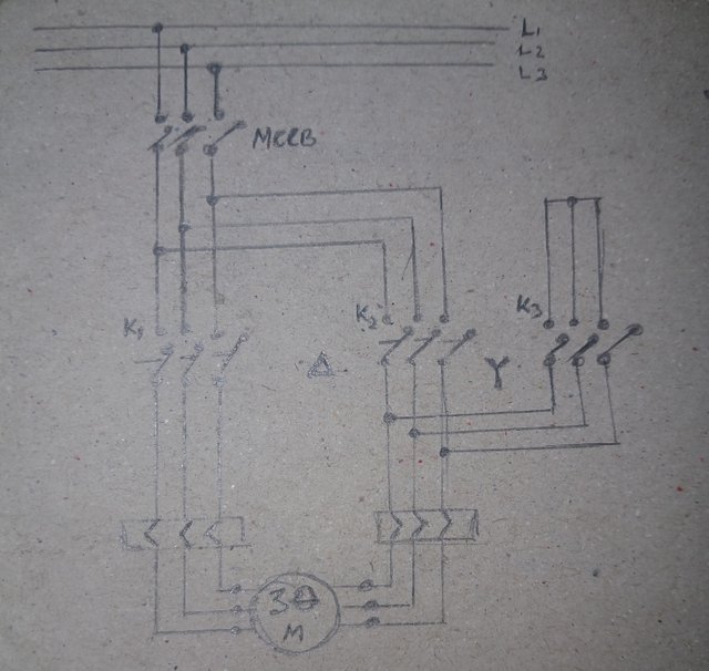
Draw the starter (power circuit) for running a 5 kW three-phase motor and write the required materials.
5 kW three-phase motor

| Material Name | Quantity | Ratings |
|---|---|---|
| Magnetic Contactor | 1 Pcs | 65 A |
| MCCB | 1 Pcs | 80 A |
| Overload Relay | 1 Pcs | 30A |
| Timer | 1 Pcs | 20-30 Sec |
Draw the starter (power circuit) for running a 45 kW three-phase motor and write the necessary materials.
45 kW three-phase motor

| Material Name | Quantity | Ratings |
|---|---|---|
| Magnetic Contactor | 1 Pcs | 200 A |
| MCCB | 1 Pcs | 200 A |
| Overload Relay | 1 Pcs | 100A |
| Timer | 1 Pcs | 20-40 Sec |
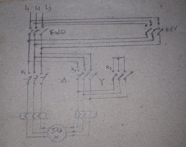
A 15 kW motor will keep the product in a fixed location. The motor must run in both directions. Draw the motor's power circuit and write down the materials required for making the circuit.
For a motor that will run both direction, we will need:
Reversing Contactors
Interlocking to prevent simultaneous energization.
Reversing Circuitry

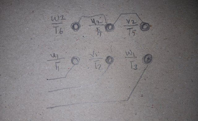
[F.] Review the pictures of the motor checked with a multimeter in my lesson and write your opinion in your own words.
A 6 point motor connector

If the result of checking the motor seems good to you, then present your reasoning.
I belive the motor is good, it did not read an infinite resistance for open circuit and the resistance was not too low close to zero, I could see 13, 11 and 30 ohms meaning the motor is good.
If you think the motor is bad, explain how you know it is bad.
[Note: Since practical work with a three-phase motor will not be possible for everyone, you have to draw the connection terminal of the motor and show it.]
I am inviting @okere-blessing, @ogechukwu-martha and @suboohi
Greetings
I have read you post, you have covered the topic beautifully and answered all the questions very well. Overall your post is very informative about industrial automation and PLC.
Downvoting a post can decrease pending rewards and make it less visible. Common reasons:
Submit