Assalamu'alaikum Everyone.
I am @kalidsyfulla , from #Bangladesh
Made by Canva
My Dear friends, how are you all? Hope everyone is well by the grace of Allah Taala. Alhamdulillah I am fine too. Dear friends, Today I came to participate in the The 23rd season of Steemians Learning Club,SLC-Home Repair Club |S23W1 ,
@imranhassan ,
@rmm31 Sir is in charge of SLC Home Repair Club.They are both advising us on this.As suggested, I created a series boards as a preliminary task to participate in the SLC Home Repair Club, which will make it easier for me to do other tasks.Below I am sharing the process of making a series board.

I purchased several appliances to participate in the CLC Home Repair Club.There were some old machines.I bought them again because they had problems.

| Products | Price | steem price |
|---|
| Soldering iron | 150 | 7.17 |
| Rung | 40 | 1.92 |
| Rozon | 10 | .47 |
| Glue gun | 210 | 10.04 |
| wire | 40 | 1.91 |
| Bord | 70 | 3.34 |
| switch | 50 | 2.39 |
| Socket | 60 | 2.86 |
| Indicator | 30 | 1.43 |
| Holder | 40 | 1.91 |
| Glue stick | 20 | .95 |
| Balp | 30 | 1.43 |

Dear friends, now I am describing the method of making a series board.

STEP 1
Dear friends, I will make the series board in such a way that I can always use it as a multiplug and use the series line while working. This is how I made the series board.
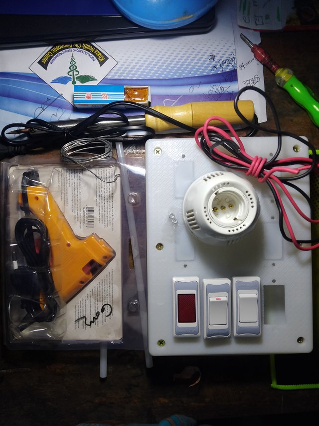
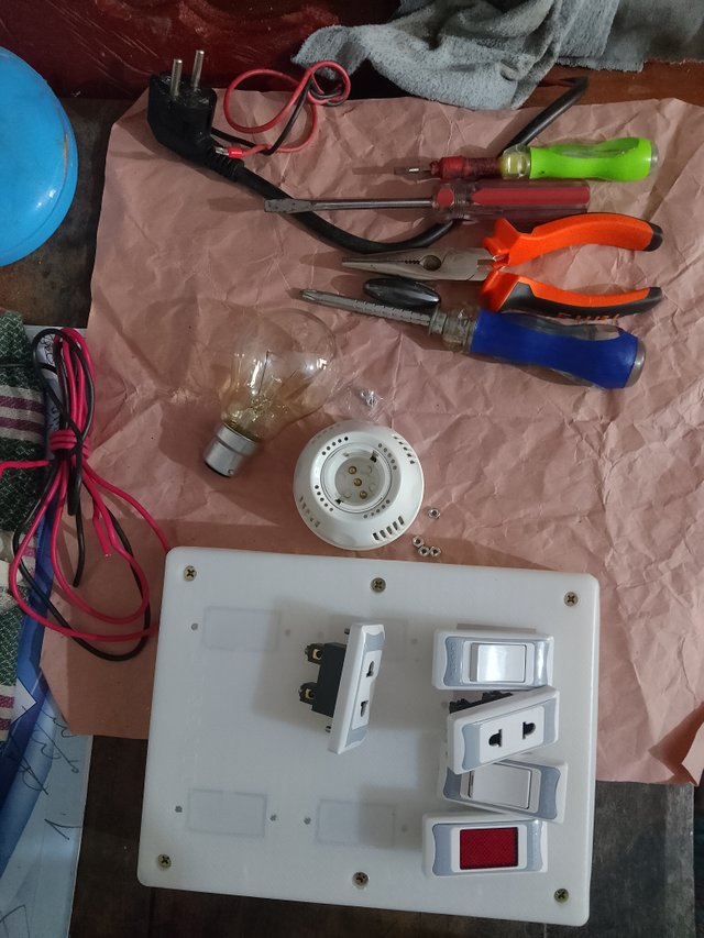
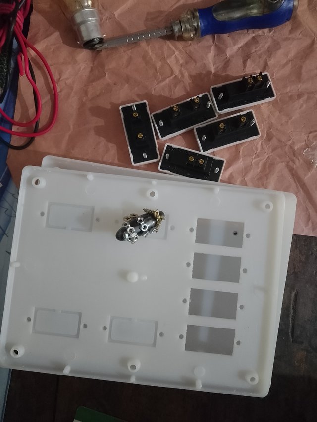
I have gathered the materials needed to make the series board in one place.Then I took the tools I needed to set them up.It contained Cutting Plus, a screwdriver, a tester, a star screwdriver, and a knife.First I unscrew the 6/8 board screws.Then I unscrewed the small nat on the switch sockets.
STEP 2
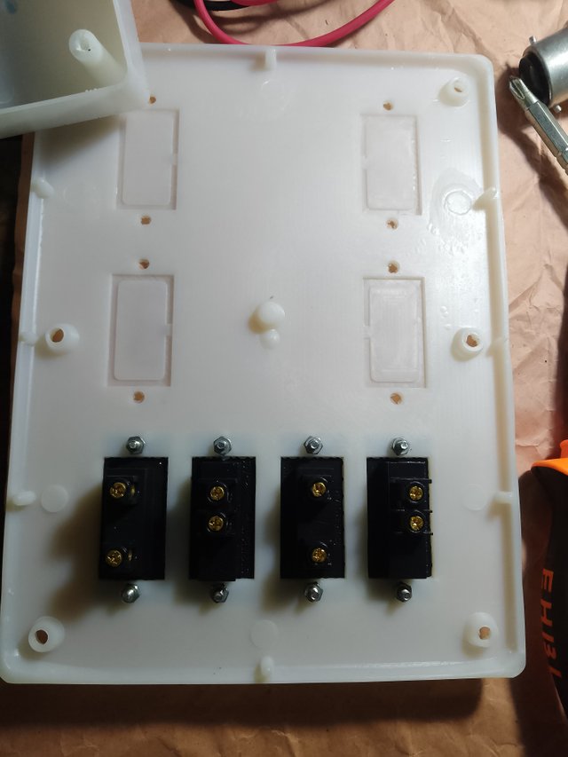
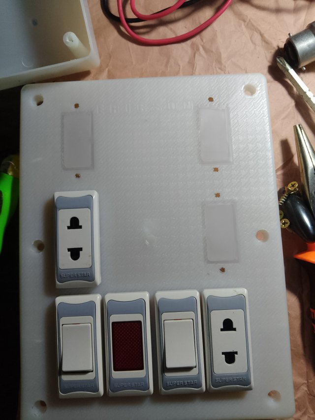
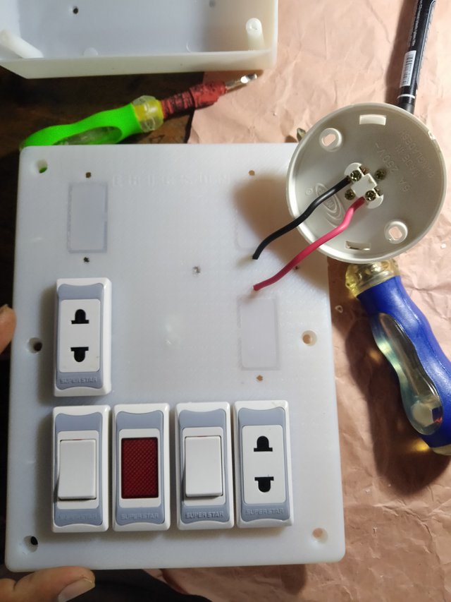
Set the switch sockets in the holes at the bottom of the board.On the left side, set a switch, then an anticator, then a switch, then a socket.And tighten the screws at the bottom nicely with pliers.To install a socket on top, use a knife to cut a hole in the board at the marked location, then install another socket there.This completes the installation of the socket switch indicator.
STEP 3
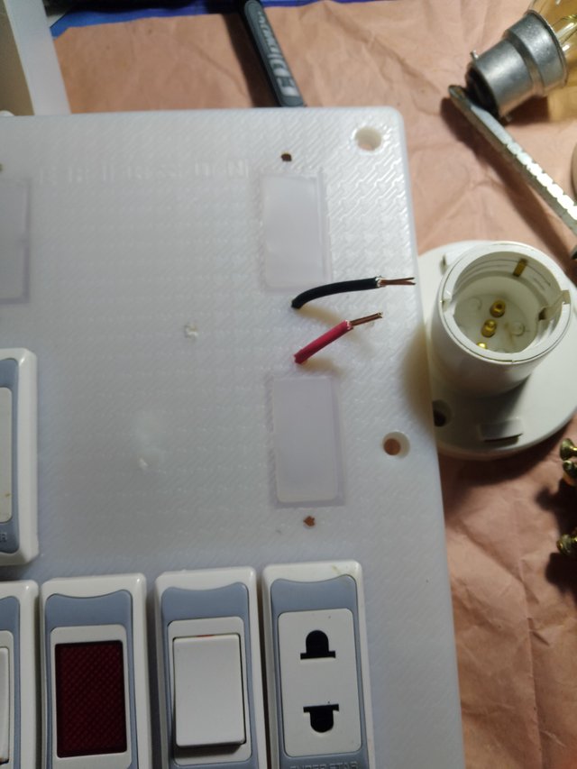
Now it's time to set the holder on the board. I noticed that before setting the holder, I have to insert the wire through the board.I first placed the holder on the board and marked the holes with a marker pen.Then I made a hole and through the hole I pulled out the red and black ones from their respective sides, facing upwards.Then I neatly attached the red and black wires to the wire setting points under the holder.Then I set up the holder on top of the board with a screwdriver.
STEP 4
 |  |
|---|
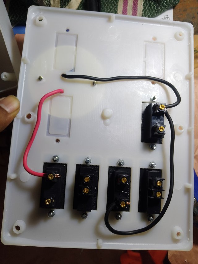
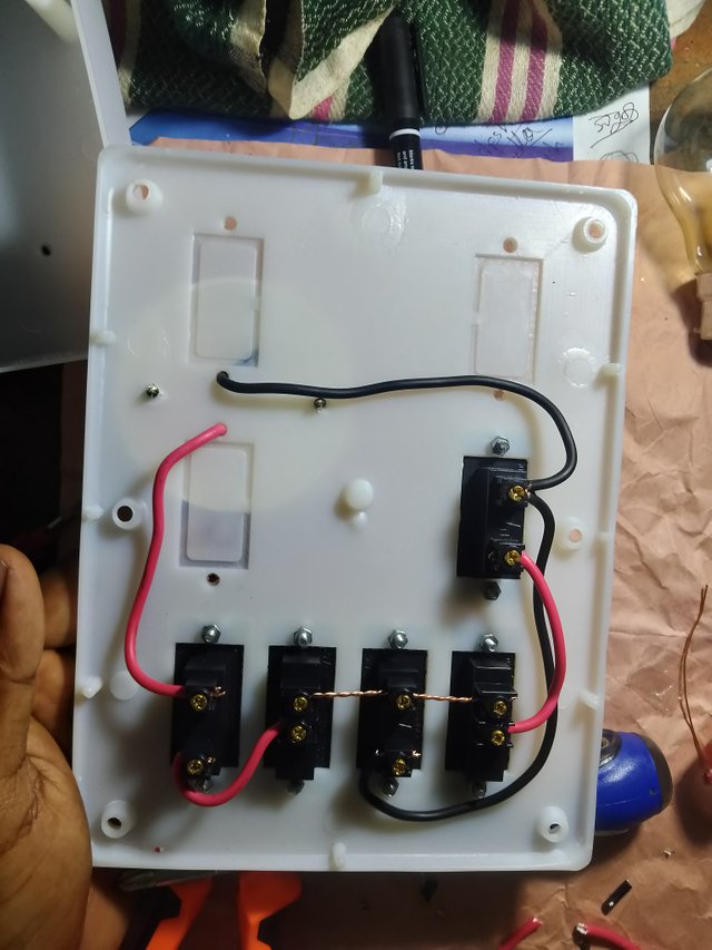
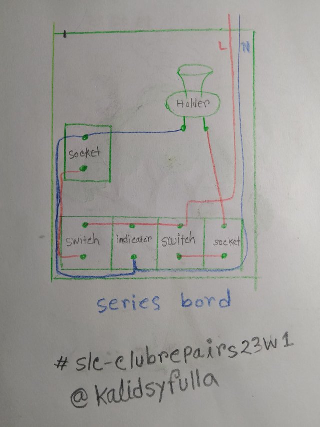
Then, to connect the switch socket of the series board, first connect the wires of the holder, connect the red wire directly to one end of the socket. And since the black wire is negative, connect it to one point of the next socket, take it out from there and connect it to one point of the lower anti-cutter.This is how I completed the negative wire connection.Then I attached the red wire from the holder, which is positive, to one end of the right side pocket.I took a wire from the other end of this socket and connected it to the bottom point of the switch.Then I connected the wires through the two switches and the points above the anticator.And I tightened the points nicely with a screwdriver.And I connected a positive line from the bottom point of the second switch to the bottom edge of the upper socket.This is how we set up the lines of the board nicely.With this latest setup, the main line of current is the negative and positive two wires.I connected the red wire to the place where I put the three switch sockets together on top.And I connected the negative black wire to my anti-knock. From here, the negative will be connected to the rest of the places.This is how I completed the work inside the series line.
STEP 5
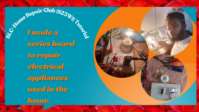
Before testing the functionality of the series board, I created an escape for the series board.Here I have shown the full details of the series board through a picture.And I wrote the username and club hashtag below the drawing.
STEP 6
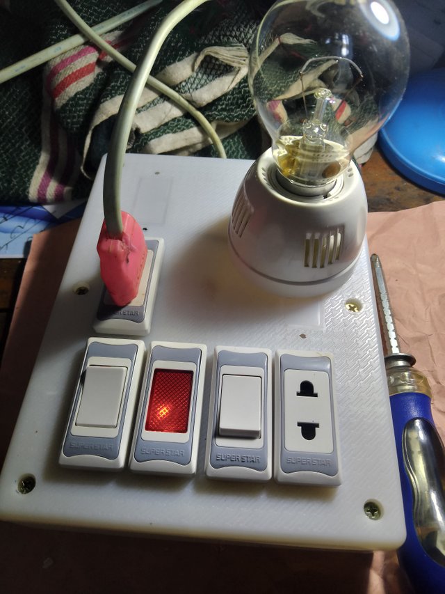
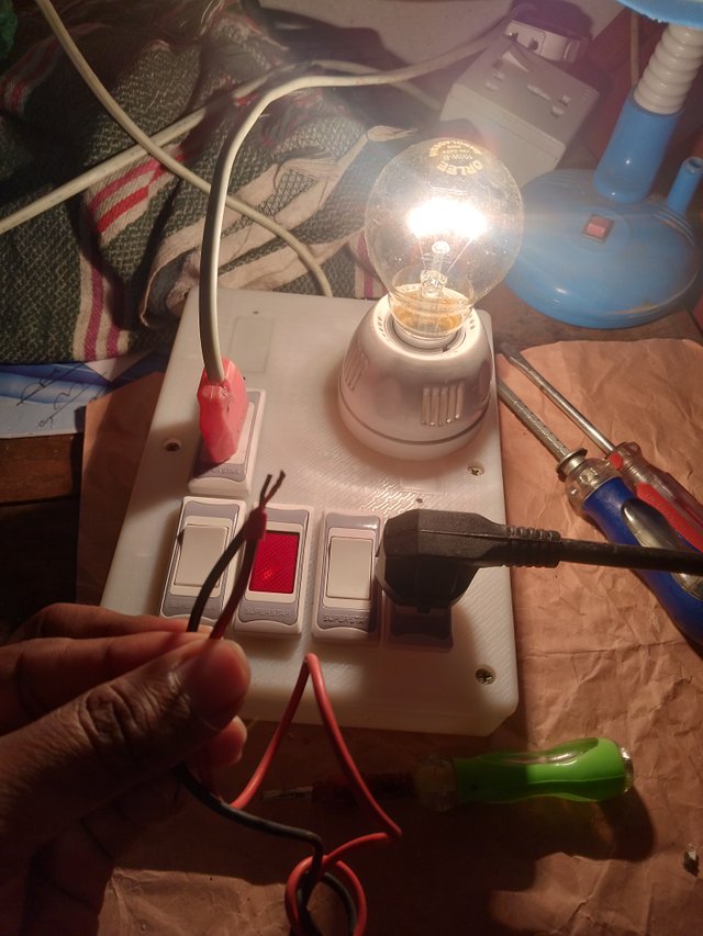
To test the series board, I first put lines on the board.Then I collected a two-pin plug.I kept the red, black, negative, and positive wires on the head of it separately.And I first put a bulb in the folder, I put a 100 watt bulb.I attached the two-pin flag to the socket that has the series line connected to it.Then I switched on the series line, then connected the two ends of the two-pin plug together and saw that the series board was working.
STEP 7
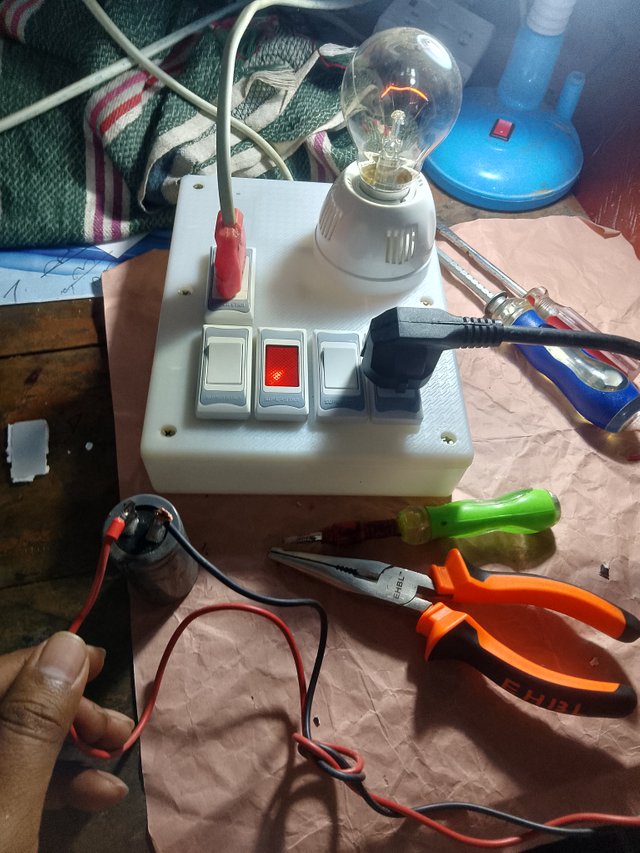
The general test I did after connecting the series board lines Then, to test further, I took an old fan capacitor and a regulator.I will now check if the capacitor is good.To test the capacitor, I tied a wire to one side of the capacitor.The output of the series board had two outputs.I tied a capacitor to that wire.I have to take a picture because if I try to test the capacitor with both hands, I won't be able to take a picture.I tied a wire for this. Then I connected the capacitor to another wire.I found that my capacitor is good but a bit weak.The capacitor was removed from the fan due to weakness.
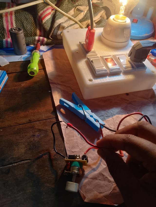
Now I will test the fan regulator with a series board.Just like before, I connected a line from the series board output to one side of the fan regulator wire with a plastic cable.Then I connected another wire of the output to another wire of the regulator.I saw that the bulb on the series board lit up as soon as I connected the regulator.Which means the fan regulator is also good.This is how I tested two things with my series board.And I successfully completed the series board creation.






https://x.com/KalidSyful53290/status/1892567382604030070?t=2MOkVajcxXpqOyrYKhfsGQ&s=19
Downvoting a post can decrease pending rewards and make it less visible. Common reasons:
Submit
Excellent work Your post is very informative and constructive. Each step is explained in detail, making it easy to understand. You have created a series board where an indicator, two switches and two socket lines are connected. In addition, the bulbs are placed in a folder, which is very useful.
Through this series board, the necessary equipment can be tested from one socket line, and it is possible to operate certain devices from the second socket line. To facilitate working from the second socket line, you can operate them with a 220-volt input line and be free from short circuits. In particular, the method of testing the fan capacitor and regulator seems to be quite effective. It will be very educational and useful for beginners.
Your hard work and presentation are really commendable. I look forward to seeing more great tutorials in the future. Best wishes.
cc: @rmm31
Downvoting a post can decrease pending rewards and make it less visible. Common reasons:
Submit
For reading my post and leaving a nice comment,And thank you very much for giving me advice.
Downvoting a post can decrease pending rewards and make it less visible. Common reasons:
Submit
I hope you will come up with more wonderful and creative projects in the coming weeks. Your work is truly admirable, and it was educational as you explained each step clearly.
Best wishes for your participation. We look forward to seeing more of your great projects in the future. Looking forward to your next participation.
cc: @rmm31
Downvoting a post can decrease pending rewards and make it less visible. Common reasons:
Submit