 |
|---|
Design by canva app
| Assalam-O-Alaikum Friends ♥️ ✨ |
|---|
How are you all? I hope you are all well. First of all, I would like to thank Prof. @mahadisalim who arranged this contest and we got to learn a new concept.
Sir, my exams were going on at university due to which I could not participate in your courses. So I apologize to you for that. There is a lot to learn from your courses.
May Allah bless you always.
A. What is meant by ladder diagram PLC programming? Draw a ladder diagram and explain? |
|---|
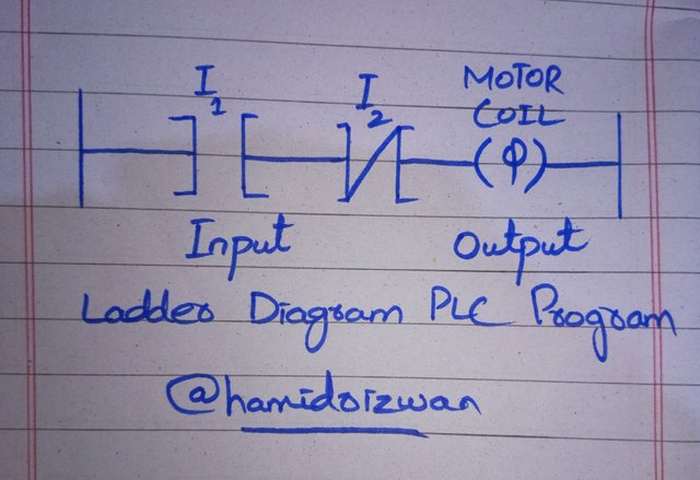
A ladder diagram is a PLC program used to convert electrical wiring into machine language wiring. We convert electrical wiring with the help of symbols. As Sir, you told us in this course we do electrical wiring to turn switch on or off.
 |
|---|
I made a picture of the ladder diagram that the professor taught us in this course. From this diagram we can see that we have two inputs and one output.
The first input on the left is denoted by (I1) and is named Normally Open. The center input is denoted by (I2) and is called normally closed. And the last one, i.e., the right side is named motor coil and it is showing the output.

B. Write the work by drawing the symbols of the input and output elements of the ladder diagram? |
|---|
| NO ( Normally Open ) |
|---|
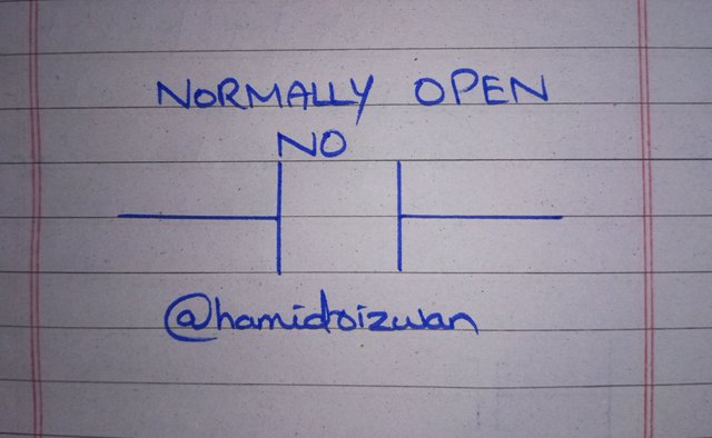
A Normally Open (NO) contact is a switch that is normally open until it is energized.
Normally Open (NO) contacts are used to turn ON a coil when a specific condition is met.

| NC ( Normally Closed ) |
|---|
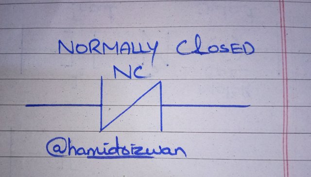
Normally Closed (NC) contact is a switch that is normally closed until it is energized.
Normally Closed (NC) contacts are used to turn OFF a circuit & coil when a specific condition is met.

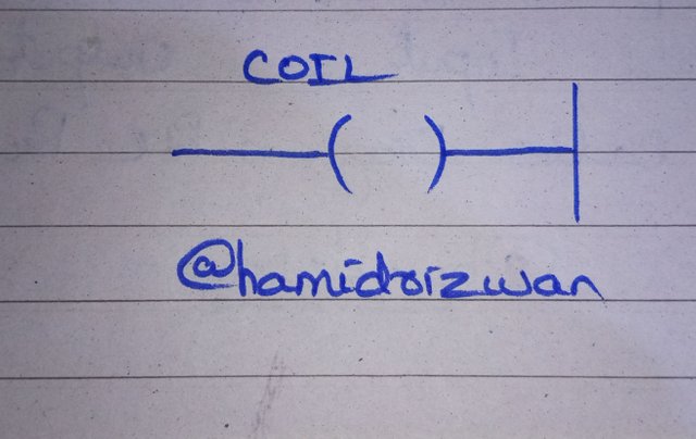
| Coil ( Output ) |
|---|
A coil is used as an output device to turn a motor on or off.

C. Draw the ladder diagram with three input ladder logic gates (AND, OR) and explain with practicals [With symbols and truth tables] |
|---|
| AND Gate |
|---|
 |
|---|
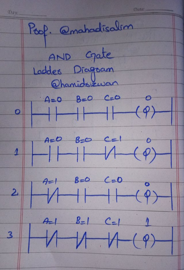
First I made a ladder diagram which consists of three inputs and one output. I denote the inputs as A, B and C.
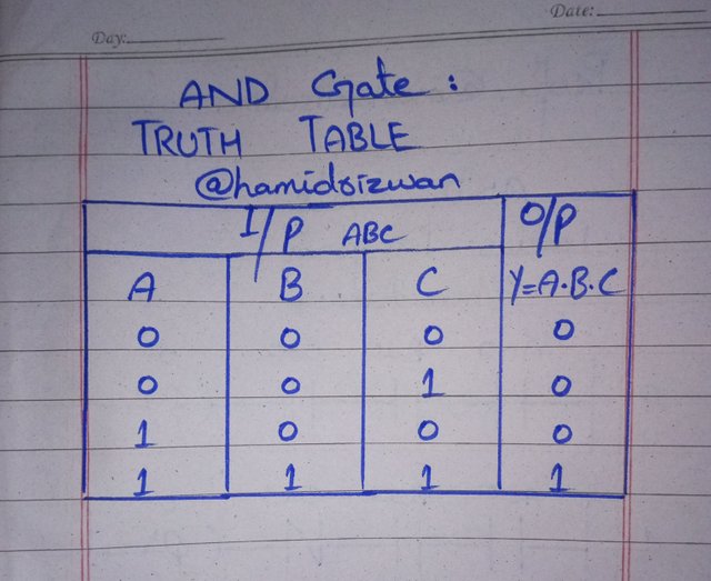
After creating the ladder diagram I also created its truth table. In truth table you will see dot, so dot means that ladder diagram is in series.
In the very first diagram I kept all three inputs open.
I mean it has all three switches off.
A = 0 ( Normally Open )
B = 0 ( Normally Open )
C = 0 ( Normally Open )
When all three switches are off, the motor coil does not supply power to the output (light) remains off.
In the last diagram of the ladder diagram I have closed all three inputs.
And in this case, I turned on all three switches.
A = 1 ( Normally Closed )
B = 1 ( Normally Closed )
C = 1 ( Normally Closed )
As soon as I turned on all three switces, the output turned on and the light would turn on.

| Truth Table for AND Gate |
|---|
 |
|---|
| Input A | Input B | Input C | Output Y = A.B.C |
|---|---|---|---|
| 0 | 0 | 0 | 0 |
| 0 | 0 | 1 | 0 |
| 1 | 0 | 0 | 0 |
| 1 | 1 | 1 | 1 |

| OR Gate |
|---|
 |
|---|
 |
|---|
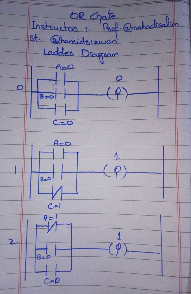
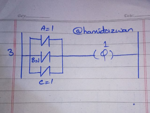
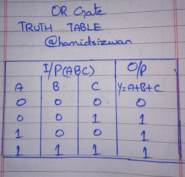
Now I explained the OR gate. And this OR gate has three inputs which I named A, B and C. And in the output I derived a formula ( Y = A+B+C ).
At this gate I used plus (+) sign. This symbol shows that the input element is in parallel.
When I connected all three switches, i.e. A = 1 B = 1 C = 1 with parallel method. So with a switch, the current flow through to the output and it turned on the motor.

| Truth Table for OR Gate |
|---|
 |
|---|
| Input A | Input B | Input C | Output Y = A+B+C |
|---|---|---|---|
| 0 | 0 | 0 | 0 |
| 0 | 0 | 1 | 1 |
| 1 | 0 | 0 | 1 |
| 1 | 1 | 1 | 1 |

D. Convert the electrical wiring in the figure below into a ladder diagram? |
|---|
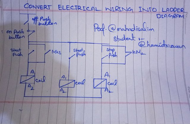 Picture copied from Instructor @mahadisalim Picture copied from Instructor @mahadisalim |
|---|
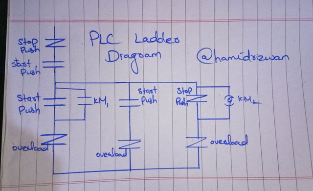 Picture created by mine Picture created by mine |
|---|
This task was very interesting. In which the electrical wiring was to be converted into a ladder diagram. Sir, after seeing the diagram you gave in the task, I made it with my own hand and shared it with you. Hope you will like it. Then I converted the electrical wiring to a ladder diagram and created another diagram that you can see above.

E. Solar power is generated in your home with three 12-volt 100 AH batteries. An additional 12-volt 100 AH battery needs to be connected as your home's electrical load increases. Explain the series and parallel connection of four batteries with diagrams. [Note: Practical can be done with multiple batteries of any rating.] |
|---|
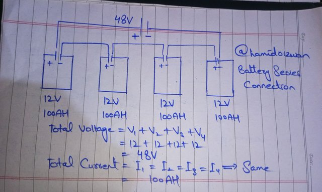
| Series Battery Connection! |
|---|
 |
|---|
First, I am going to explain the battery with a series connection. As you guys know, a battery has two terminals positive and negative. I took four batteries and connected the positive terminal to the negative terminal. I took four 12 volt batteries. Which you can see in the diagram.
| Calculate Total Voltage |
|---|
Using Formula!
Total voltage = V1 + V2 + V3 + V4
V = 12
= 12 + 12 + 12 + 12
| Total Voltage = 48 |
|---|
| Total Current = ? |
|---|
Total Current = I1 = I2 = I3 = I4
100 = 100 = 100 = 100
Total Current = 100AH

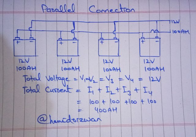
| Parallel Battery Connection |
|---|
 |
|---|
Then Sir, I made another diagram. And in this I connected the batteries in parallel ways. I took four 12 volt batteries. Now I have to find the total voltage and total current in these batteries? So for this I will use a formula. That is what the instructor told us in this course.
Total Voltage = ?
| Using Formula |
|---|
Total Voltage = V1 = V2 = V3 = V4
Total Voltage = 12
| Voltage remain same |
|---|
Total Current = ?
Total Current = I1 + I2 + I3+ I4
= 100 + 100 + 100 + 100
Total Current = 400 AH

| Invite friends |
|---|
@gondalbiya, @seharsharif and @suryati1
Best Wishes 😍 Always be happy.


💦💥2️⃣0️⃣2️⃣5️⃣ This is a manual curation from the @tipu Curation Project
@tipu curate
Downvoting a post can decrease pending rewards and make it less visible. Common reasons:
Submit
Upvoted 👌 (Mana: 5/6) Get profit votes with @tipU :)
Downvoting a post can decrease pending rewards and make it less visible. Common reasons:
Submit
Terimakasih temanku atas undangannya, semoga anda beruntung teman 🌹
Downvoting a post can decrease pending rewards and make it less visible. Common reasons:
Submit