Greetings Steem Infinity Zone from @ammar79

I started Robotics, IoT, and home automation course here. Today is our 2nd lecture. in My previous lecture. I described the Basics of IoT and microcontrollers then connected and configured the esp32 microcontroller with Laptop.
For Beter Understanding I also Make a video Tutorial for this lecture.
here is the link to my first lecture
Lecture 01!
in today's lecture, we will continue our previous lecture and some interesting programs.
Lecture Outline
1. Blink a led
2. Serial Communication
3. Interface Oled Display with The Microcontroller

1. Blink a led
.jpg)
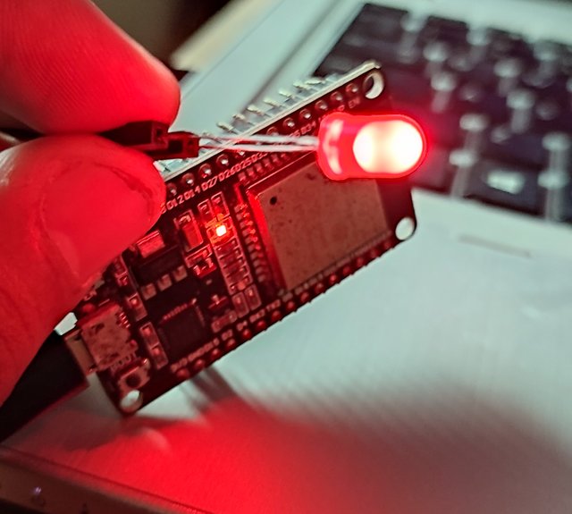
Almosts in all projects we require an led for indication. So initially we have to learn how to On to OFF aLED on condition Base here Is the cod for blinking LED
const int ledPin = 15;
void setup() {
pinMode (ledPin, OUTPUT);
}
void loop() {
digitalWrite (ledPin, HIGH);
delay(500);
digitalWrite (ledPin, LOW);
delay(500);
}
Now let's Explore this Code
const int ledPin = 15;
here we storing a Pin Number in with we are going to connect LED

void setup() {
pinMode (ledPin, OUTPUT);
}
Here we are reserving the mentioned pin for output

void loop() {
digitalWrite (ledPin, HIGH);
delay(500);
digitalWrite (ledPin, LOW);
delay(500);
}
This is a loop Function here we powering up our reserved pin as high and after 500 Microsecond Delay, we are setting power low on this pin, and again after 500 microseconds, again our light will be on, and so on according to the loop. This is an infinite loop so it will be never end
in our code "HIGH" represents on and "LOW" represents off

2. Serial Communication
In my Previous Lecture I Described how to Recieve Data From Serial Communication here I will Describe it More Deeply.
here is the code for sending data to the microcontroller through Serial Monitor
#include <Arduino.h>
String command;
void setup() {
Serial.begin(115200);
}
void loop() {
if(Serial.available()){
command = Serial.readStringUntil('\n');
Serial.printf("Command received %s \n", command);
}
}
Now, We will explore this Code.
#include <Arduino.h>
String command;
void setup() {
Serial.begin(115200);
}
here we are Including a Header file. Then declaring a string variable. in Our Setup Function. we are initializing Serial Port with 115200 Baud Rate. Baud Rate is the main concept of Serial communication we basically telling our Microm controller to send or receive data through this baud rate. If we have a difference in baud rate in our PC and Microcontroller then we will receive garbage data. That's why we need to select the baud rate in our Serial Monitor as same we mentioned our code

void loop() {
if(Serial.available()){
command = Serial.readStringUntil('\n');
Serial.printf("Command received %s \n", command);
}
}
Now In the loop function, we are checking Data Availability On the serial port from our PC. If data comes from PC then the next code is to store whatever data we received into our declared String Variable.
then in the last Statment, we are printing the same Data into serial Monitor with the concatenation of "Command received" string

3. Interface Oled Display with The Microcontroller
Now we came to the most interesting part of this lecture. now we will interface display with our ESP32Board
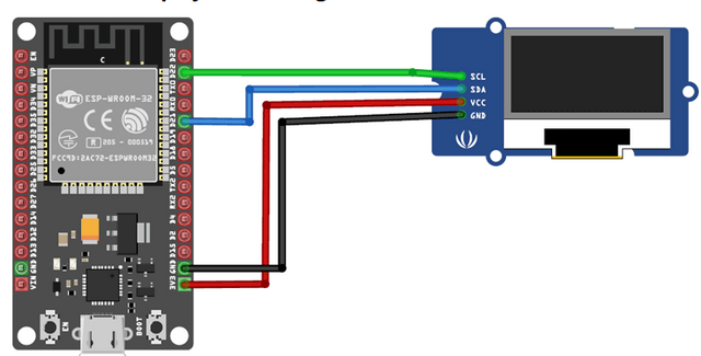
here is the Pin Configuration you have to connect all four pins same as the below diagram. I used Female to Female jumper Wires to connect LCD with Microcontroller

Now let's come to Our Code
#include <Wire.h>
#include <Adafruit_GFX.h>
#include <Arduino.h>
#include <Adafruit_SSD1306.h>
String command;
#define SCREEN_WIDTH 128 // OLED display width, in pixels
#define SCREEN_HEIGHT 64 // OLED display height, in pixels
Adafruit_SSD1306 display(SCREEN_WIDTH, SCREEN_HEIGHT, &Wire, -1);
void setup() {
Serial.begin(115200);
if(!display.begin(SSD1306_SWITCHCAPVCC, 0x3C)) { // Address 0x3D for 128x64
Serial.println(F("SSD1306 allocation failed"));
for(;;);
}
delay(2000);
display.clearDisplay();
display.setTextSize(2);
display.setTextColor(WHITE);
display.setCursor(0, 0);
display.println("@AMMAR79");
display.setTextSize(3);
display.setCursor(30, 30);
display.println("SIZ");
display.display();
void loop() {
if(Serial.available()){
command = Serial.readStringUntil('\n');
Serial.printf("Command received %s \n", command);
display.clearDisplay();
display.setTextSize(2);
display.setCursor(0, 0);
// Display static text
display.println(command);
display.display();
}
}
Let's Explore this Code
#include <Wire.h>
#include <Adafruit_GFX.h>
#include <Arduino.h>
#include <Adafruit_SSD1306.h>
String command;
#define SCREEN_WIDTH 128 // OLED display width, in pixels
#define SCREEN_HEIGHT 64 // OLED display height, in pixels
Adafruit_SSD1306 display(SCREEN_WIDTH, SCREEN_HEIGHT, &Wire, -1);
This is our header Section here we are including Header files from Library. For Including Header File you Must have a Library containing that header file and dependencies. Hopefully, you can Download and install the library easily from Arduino IDE for This Just go to Sketch on the menu bar and select include a library and then select manage libraries. in a new dialogue box just search header file name without .h and you will find the required library just click on install to install it repeat this for all libraries
after Header Files, We are Defining some Global Contents by storing the size of our LED then we are initializing our Display with the unction already provided in the header file.

}
delay(2000);
display.clearDisplay();
display.setTextSize(2);
display.setTextColor(WHITE);
display.setCursor(0, 0);
display.println("@AMMAR79");
display.setTextSize(3);
display.setCursor(30, 30);
display.println("SIZ");
display.display();
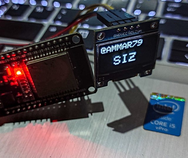
Here is the code to Display text on the LED. firs we will clear Display so we called that method then we set the font size and colors. After that, we are setting cursor Position and Hard quoted text want to display. the same process repeated for the next line.
here is the OutPut f Mentioned Code
.jpg)

Now Next in Loop Function
void loop() {
if(Serial.available()){
command = Serial.readStringUntil('\n');
Serial.printf("Command received %s \n", command);
display.clearDisplay();
display.setTextSize(2);
display.setCursor(0, 0);
// Display static text
display.println(command);
display.display();
}
}
here we are Printing any data that we get from Serial Port in scree. we used the Same code which we already used in the serial monitor this time we also displayed that string on or display. when we power up our microcontroller first it will display text written in the setup function then come to loop and prin whatever we send to our microcontroller through the serial port
Waiting for your reviews on Comments


Good one Post dear friend you make a very good post thanks for sharing a good information with us my best wishes for you. Keep it up bro and keep learn with our steem fellows.
Regards, Faran Nabeel
You can delegate your SP to @siz-official and take benefit of our Delegation Offer getting up to 200 % Curation rewards
501002003004005001000200030004000500010000
Downvoting a post can decrease pending rewards and make it less visible. Common reasons:
Submit