Today I have worked on @kouba01's SLC S23 Week1 || Computer Repair - Power Supply challenge, a super interesting topic and helpful if you own a PC and you'd like to learn more about it, if you are interested you can take a look and who knows, you might like it enough to join it.
Image taken from Pixabay
Since my PC was bought as a prebuilt and it's still in warranty I wouldn't like to mess with it's PSU because as a prebuilt if anything happens I have to send the whole PC to warranty (stupid policy if you ask me), I wouldn't be able to send just the PSU. That's why I am going to use another smaller PC for today's tasks, I am going to do some "experiments" and I don't really care if this PSU breaks or anything. I have bought this small PC from a yard sale a couple of months ago, it's pretty old, it comes with a 2nd generation Intel i3, 4GB DDR3 and an HDD. I added an old SSD to it just to test it and I am keeping it for a later project, I thought about running a Steem Bot on it instead of getting a VPS, but that's for a later post.

- Examine the power supply unit of your computer or any other device and determine its type. Then, refer to the label on the unit to identify and note its input and output voltage specifications.
Today we are going to work with this "bad boy", a PSU from Antec, precisely the FP-150-8 Model. The PSU is a Flex ATX rated at an output of max 150W. Most of the people that have a PC probably heard about ATX PSUs but probably only a few about Flex ATX ones. The main differences between those 2 are related to their sizes Flex ATX are more compact and have less expansion possibilities, usually used for compact PCs and small servers while ATX are mainly used in Gaming PCs and workstations where the output is much higher.

Antec FP-150-8
Details of the power supply:
| Name and Model | Antec FP - 150 - 8 Model |
|---|---|
| AC Input | 100V - 240V 3A - 1.5A |
| Frequency | 47Hz - 63 Hz |
| Output | Max 150W |
| Modular | Non Modular PSU |
| DC Output | + 5V | +3.3V | +12V | -12V | +5VSB |
|---|---|---|---|---|---|
| Max. | 10A | 8A | 10A | 0.2A | 1.5A |
5V, 3.3V, 12V, -12V, +5VSB are all voltage rails that are used to supply the components in your PC while the numbers below the voltage 10A, 8A, 10A, 0.2A, 1.5A represent the maximum current measured in Amps that each voltage rail can provide.
Here is an example for the 12V, for this one we have a max of 10A which if we do the math 12V * 10A we get a max power of 120W, 12V being used for the components that usually use lots of power, CPU and GPU as an example.

- ATX power supplies supply power to ATX cards through a 24-pin connector. List the wire colors used for each number in the following table.
For the second task I took the picture @kouba01 created for the ATX pins, moved it into photoshop and colored the background of each cell to it's corresponding color and also added some text above it mentioning the corresponding color.

Each corresponding Wire with it's own Voltage is used to power something:
- (+ 3.3V 🟠) - Used to power the Chipset (The chipset is a group of integrated circuits that manages the data/communication between the PC components CPU/GPU/Storage/RAM/Periphericals etc.), RAM, PCIe slots.
- (+ 5V 🔴) - Powers the USB Ports and HDD/SSD
- (-5V ⚪) - Now obsolete, it was used for old expansion cards, old sound cards, legacy communication hardware (ex. modems)
- (+ 5VSB 🟣) - SB comes from Standby and powers the USBs even when the PC is off, also used for Wakeup On Lan
- (+ 12V 🟡) - Powers the CPU, GPU, Cooling Fans, usually the things that demand much power
- (- 12V 🔵) - Used for legacy components, some network cards and serial ports that were used before the USB came out
- (PS-ON 🟢) - when connected to ground it turns on the PSU
- (PW-OK [didn't find a Grey Circle]) - Power Good, used to send signal to the MOBO when everything is stable, prevents starting issues
- (GND ⚫) - Ground
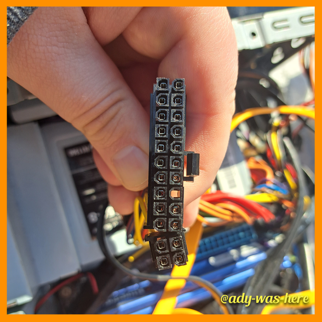
Here's a picture with my current ATX connector of this PSU.
You can see that the (- 5V Pin, white cable, number 20 in the table) is missing, it's an empty space there.

- Look at the image above showing different power connectors on a computer power supply. Match each numbered connector to its specific use based on the information provided. Then, explain the role of each type of connector in the operation of computer components.
I will create a table for each connector, what it is used for and some details about it, not sure if I am allowed to replace @kouba01's connectors with picture from mines, so I will crop each one individually and add them below, anyway if I were to replace them I don't think I have a Floppy Disk Drive one to show.
| IMAGE | Connector_1 | Split 4 + 4 Pin CPU Connector |
|---|---|---|
 | Description | It's a split connector that can be used as a 4 - pin connector (usually used for older motherboards) and an 8 - pin one for newer ones. Based on the slot you have you can connect only one 4 - pin or both. |
| IMAGE | Connector_2 | 8 Pin CPU Connector |
|---|---|---|
 | Description | A connector used to power the CPU, it connects to the 8 pin slot on the motherboard, if your motherboard has only a 4 Pin slot you can use an adapter/converter from 8-pin to 4-pin, or simply plug just one site of the connector. |
| IMAGE | Connector_3 | 6 Pin GPU Power Connector |
|---|---|---|
 | Description | A connector used to give extra power to a GPU, by default the PCIe x16 provides a maximum of 75W, some cards require much more power, here comes the 6 Pin Connector to help deliver more power to the GPU, the 6 Pin adds another 75W power when needed. |
| IMAGE | Connector_4 | 6+2 Pin GPU Power Connector |
|---|---|---|
 | Description | Does the same as a 6 Pin Connector but if it is used as a full 8 Pin connector it brings 150W to the table (75W extra compared to 6 Pin), this should not be confused with the 8 Pin CPU one. |
| IMAGE | Connector_5 | SATA Power Connector |
|---|---|---|
 | Description | It's the younger brother of IDE connector, used to power HDDs, SSDs, Optical Drives and in some cases Fans and RGB controllers, the SATA Power Connector comes with 15 pins while the smaller version (7-Pin) is used for the data transfer. |
| IMAGE | Connector_6 | Molex |
|---|---|---|
 | Description | A connector that isn't used that much nowadays, it was used before SATA to power older HDDs and Optical Drives. These days you can see it in the cheaper cases used to power fans or rgb controllers. |
| IMAGE | Connector_7 | Floppy Connector (known as Berg 4-Pin Connector) |
|---|---|---|
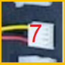 | Description | Floppy Power Connector used to power floppy disk drives, nowadays since people stopped using Floppy disks it could be used as a fan controller or rgb controllers. |
| IMAGE | Connector_8 | ATX 24 Pin / ATX 20+4 |
|---|---|---|
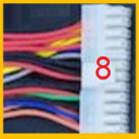 | Description | The main power connector that supplies the power to the motherboard. It started as a 20 - Pin but now that is the older standard, currently we are using 24 - Pin or 20+4 Pin (Modular) because the systems now require more power. |

- What are the common signs that a computer power supply is failing, and what steps should you take to diagnose the problem before replacing the power supply?
There are many signs that a PSU is failing I will list some below and I am sure some of you readers encountered at least one of these at one point:
- the PC doesn't power on, you press the button and there's no noise, no movement
- PC shuts down (or restarts) randomly and it happens most of the times under high load
- strange sounds/smells coming from the PSU
- PC is being unstable, the CPU or GPU doesn't perform at full capacity
Of course the list can go on there are many other things that a faulty PSU can generate, this is a general list with the common issues.
Now how would I diagnose it, well here comes the "experiment" part I mentioned at the start of the post, I'll show you how I'd do that.
Firstly the simplest things to check are the socket and the power cord, you can either test the socket with another device or plug the PC in another socket, if the problem isn't here you can check the power cord. To check the power cord you can use a Mains Tester screwdriver like this:

I did the testing outside and the light is barely visible not sure if you can see it in the picture. If everything is ok the next thing we can use to test the cord is a multimeter, I have this one that I've used.

The multimeter I used
We can check with this tool the voltage between N and L and see if it's correct and if we are here we can also test between Ground and L.
- N (Neutral)
- L (Line/Live)
| N(Neutral)/L(Line) | Ground/Line |
|---|---|
 |  |
Also forgot to mention that the multimeter can have a 4% error in it's readings, at least that's what the manual says.
You can open the images in a new tab to see them in full size (1080 x 1080px)
Now that we cleared the socket and power cord we can test other connectors, the first one that should be checked is the ATX (24 / 20+4) one. With the PSU connected to the socket we can use the multimeter to test the Power On Pin and a Ground Pin, if the result is 5V it's working ok.
Used the multimeter on the Power On (Pin nr 16) and Ground (Pin nr 17)
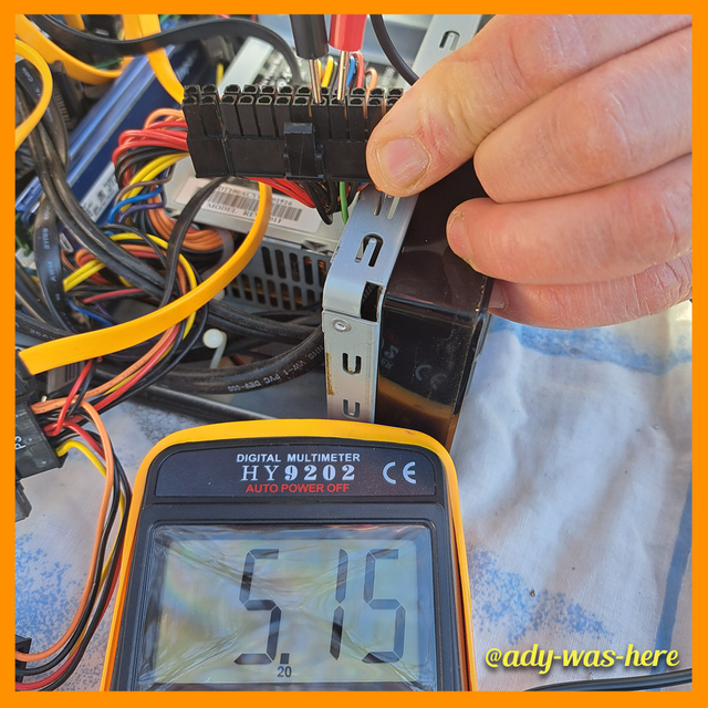
In this case we get 5V and it works ok
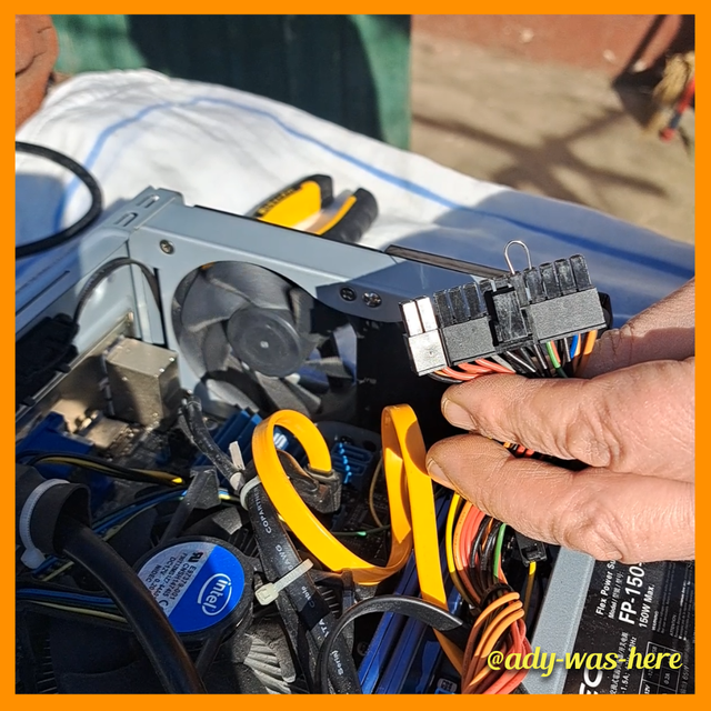
Now to further test everything let's start up the PC, in order to achieve a good start up I am using a paper clip to keep the Pins mentioned above connected (16 & 17 / Power ON and Ground).
| Paper Clip | ATX with Paper Clip |
|---|---|
 |  |
Here's a GIF from the recording I did, the PSU is connected to the socket and once the paper clip is being inserted you can see in the background on the left side the fan starts spinning, meaning the PC powers on.
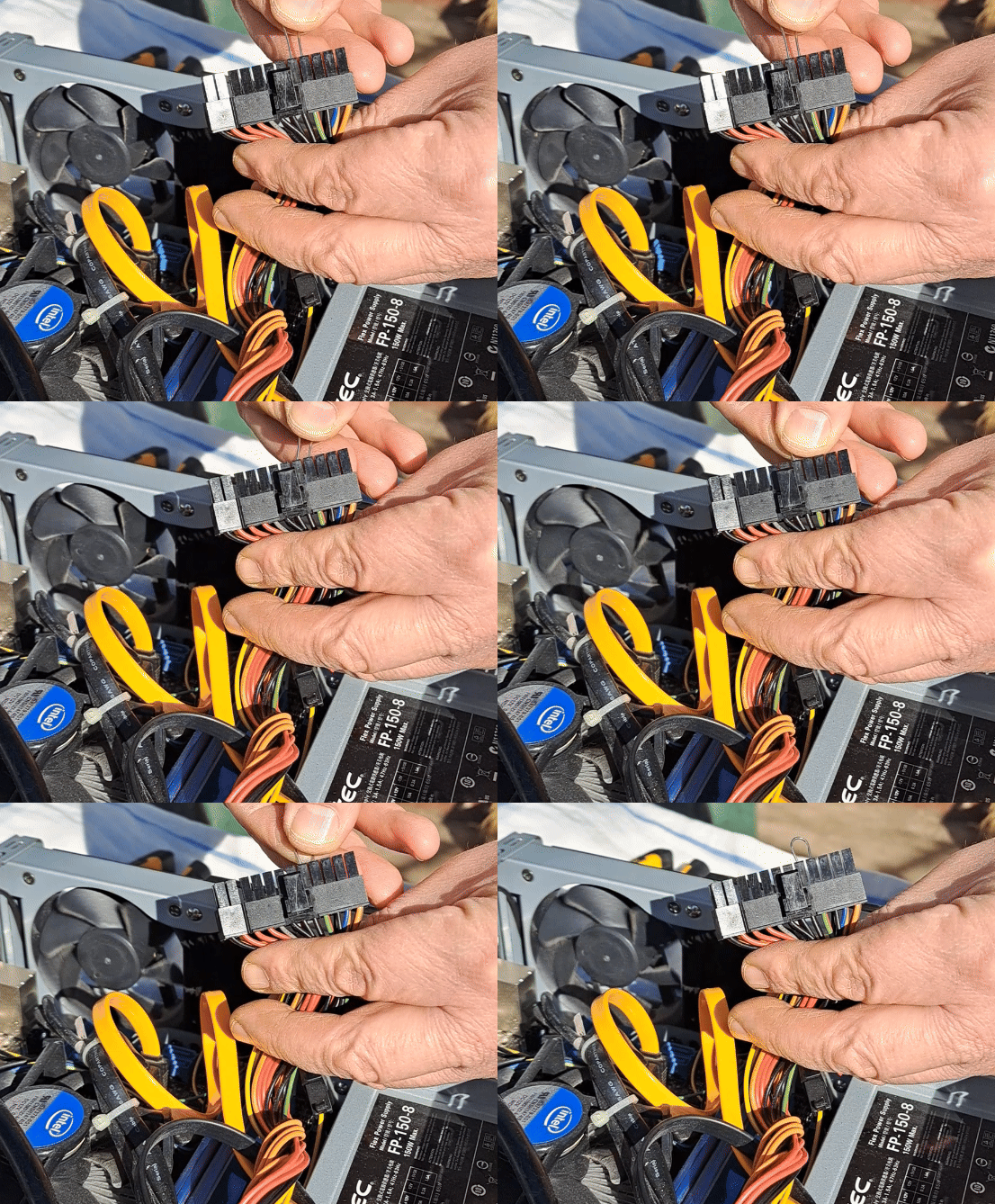
IT'S ALIVE! Now that we have some movement we can start checking the other Pins of the ATX connector, I'll show you some examples:
| 3.3V 🟠 and ⚫ | 12V 🟡 and ⚫ |
|---|---|
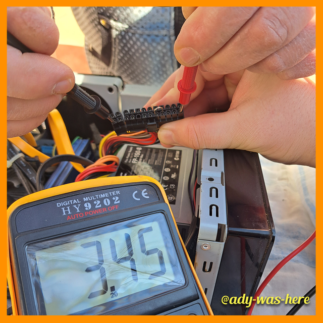 |  |
3.3V 🟠 and ⚫
The measurement done between Orange 🟠 and Black ⚫, you can see the result is close to 3.3V we need to consider the 4% error of a multimeter.
12V 🟡 and ⚫
The measurement done between Yellow 🟡 and Black ⚫, you can see the result is 12V.
| 5V 🔴 and ⚫ | 5VSB 🟣 and ⚫ |
|---|---|
 | 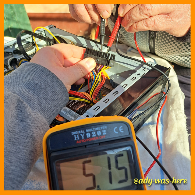 |
5V 🔴 and ⚫
The measurement done between Red 🔴 and Black ⚫, it results in 5V which is correct.
5VSB 🟣 and ⚫
The measurement done between Purple 🟣 and Black ⚫, it results in 5V which is correct.
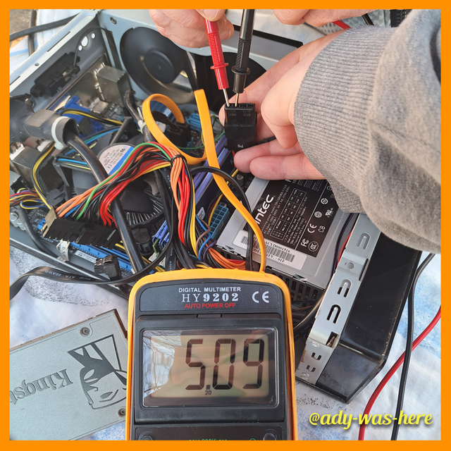
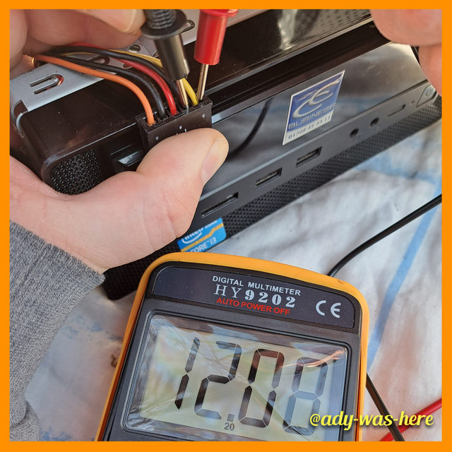
Since we are here, I wanted to leave this remark here, you can use the same logic when testing other connectors of the PC, here are two more examples one Molex and one Sata, you need to make sure you respect the colors and their values and always pair them with a Ground.
| Molex | Sata |
|---|---|
 |  |
These are the steps I'd take to check a faulty/failing PSU, the important one where I'd probably change it already is the paper clip test, if it fails that one I wouldn't have the courage to use it in my PC even if I'd get it fixed, with the current PSU prices it's not worth the risk.

- What precautions and best practices should be applied when maintaining and cleaning a power supply to ensure its proper functioning and extend its life?
Note: Any maintenance/cleaning on the PSU should be done with the PSU unplugged from the socket! Even if you turn off the PSU by the back button/switch, an unknown fault of the PSU might harm you!
First things first, it's a common practice to use an anti-static wrist strap or a grounding pad while working with electronics as static discharge can damage electronic components, it's not the case with the newer PSU as they come with a big load of protections but still if you want to be sure you can use one. Or you can simply touch a grounded metal and you will discharge but while working based on what you are touching/clothing you can charge up again.
| Anti Static Wrist Wrap | Grounding Pad |
|---|---|
 | 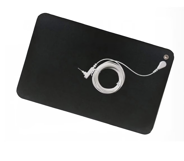 |
Both pictures were taken from Pixabay
There are some things that you can do to increase the lifespan and ensure the PSU is working properly:
- One of the first things that increases the lifespan of a PSU is the cleaning part, a PSU that is not being cleaned regularly can get overheating issues, by cleaning it you make sure it gets proper ventilation. There are PSUs with dust filters in which makes the cleaning part easier as you can get the filter out clean it and add it back to the PSU but usually these come with the pricier PSUs.
- Avoid moisture and cleaning it with liquids, you can easily short circuit it but in extreme cases in time it can cause corrosion. Anything that can blow air (compressor/vacuum cleaner) should be enough to blow the dust/debris out, you need to be careful with one thing here, if you blow the air close enough and with a high force you should keep the fan blocked so it won't spin
- Use an UPS or Voltage Regulator (not sure if this is the correct English term), using these you can save your PSU from Voltage Variations and Power Outages.
- Making sure the PSU can provide enough Power for the system components you are using, running it at below 85% of it's power can increase it's life.
Now some things I want to mention about the cleaning part, this being the essential one it should be done accordingly, you can do it as often as you feel necessary, if you are doing it every 6 to 12 months it should be more than enough, the newer PC cases come with filters so there shouldn't be a problem with the dust as it used to be in older PCs.
The steps should be like this:
- Power Off the PC and disconnect/unplug it from the socket
- Hold down the Power Button 10-15 seconds to discharge the power left
- Avoid cleaning with liquids, instead use compressed air to blow the dust out
- You an also use an anti-static brush and/or microfiber cloth depending on the case
When you blow the dust out make sure to do it in bursts and not blow continuously, make sure you blow from both directions to get out more dust.
Also I used canned air (compressed air) to clean keyboard at one point and at one point it started "spitting" liquids, I'd avoid using it for PSUs if you have an alternative (vacuum cleaner/compressor).
I wanted to include some cleaning GIFs here but the PSU being that small you can barely understand anything from the GIFs I created, you can't see the dust coming out while I am blowing it out.
Now that we got to the end of the challenge, I want to tag @mojociocio in case he wants to join too, I know he has a beast of a PC, he would surely show some fantastic shots while creating the post.
Thank you @kouba01 for this class, can't wait to see what you have prepared for next week. Until next time I am wishing you a great day everyone!
Congrats.....
Your explanations are to the point. I liked the coloring of the photos you captured from your camera. Please can you tell me about the camera or mobile version that you used to capture photos? Also about the software you used to edit the Task banners like task 1, task 2 and so.
Downvoting a post can decrease pending rewards and make it less visible. Common reasons:
Submit
Hello @ghiasahmad, thank you!
I used a Samsung A53 to take the photos/video a pretty old phone but still gets the job done, I had to resize the pictures from 3468 x 4624 to 1080 x 1080 as their size was too big and would make the post loading a little bit longer. As for the task banners I used Adobe Illustrator to create them.
Downvoting a post can decrease pending rewards and make it less visible. Common reasons:
Submit
Wow.....You are such a creative person my dear. 🤗
Downvoting a post can decrease pending rewards and make it less visible. Common reasons:
Submit