Good day to the electronic team.
Circuit is a path that allows the flow of electric current. A circuit must have a battery and wire to transmit energy.
Proper interpretation of circuit diagram make it easy to build a circuit
Task 1:
Do the both connections with or without a breadboard, but it is more advisable to use a breadboard since we would be using it all through. Write your observation for the first experiment and diagram, do the same with the second.
Connections are done without breadboard
Diagram 1
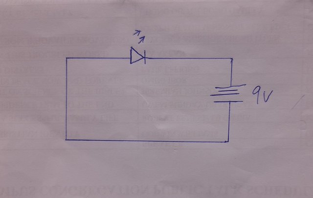
Image from @ubongudofot
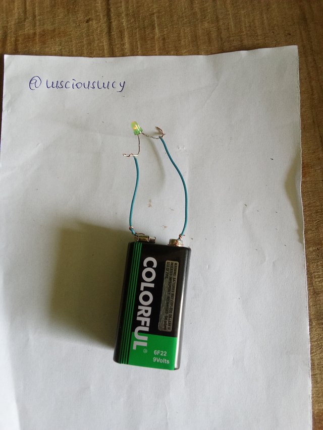
Observation
- When LED was connected directly to the battery, the LED indicated red light. The voltage of the battery is higher than the LED.
- Probably the battery voltage has dropped reason why the red light is not so bright which can blow up the LED.
Diagram 2
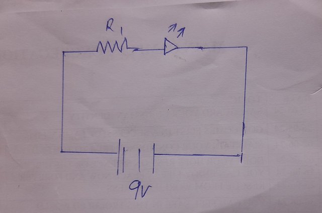
Image from @ubongudofot
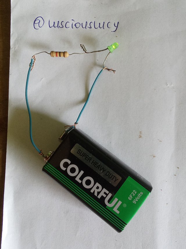
Observation
- Since the LED is not directly connected to the battery, the connection of the resistor neutralize the energy of the battery to the LED making it to shine a green light.
Task 2:
Draw a circuit diagram of a LED attached to 2 resistors of 1k ohms connected in series, powered with 9V battery source. What steps did you take in drawing this?
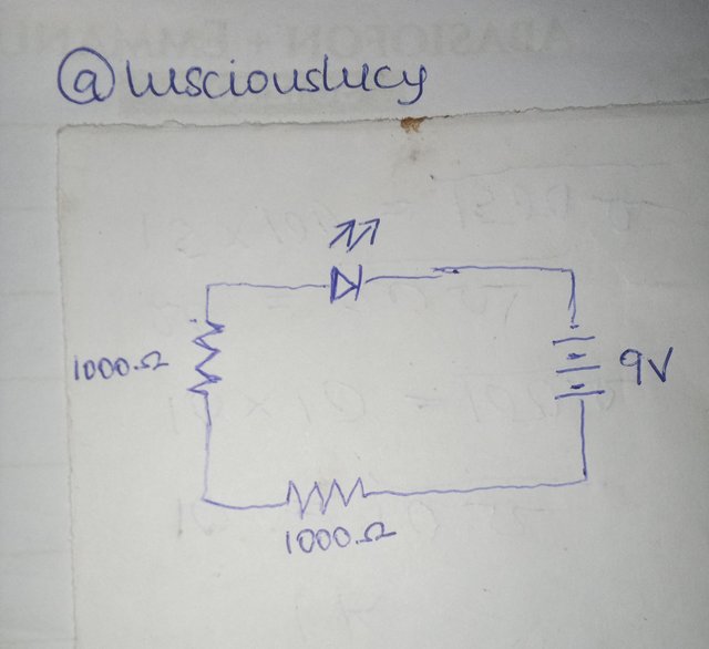
Steps
- Understanding the task
- Knowing the symbols of LED, resistor and battery.
- Drawing the resistors, LED and battery and connecting it with a jumper wire.
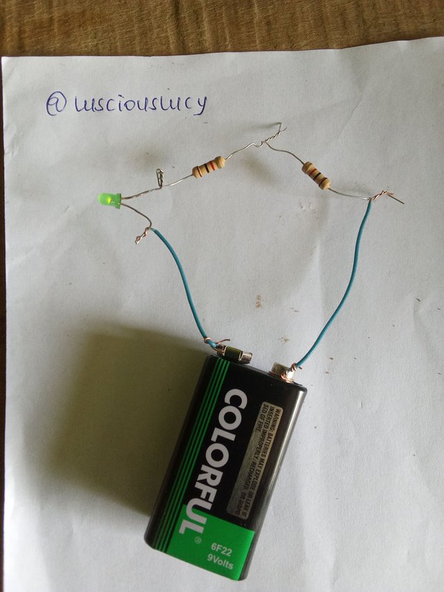
Did the connection and the LED emitted a dimmer green light because of the 2 resistors connected.
Task 3:
Explain the two circuits below, state their differences if at all there is any
Circuit 1
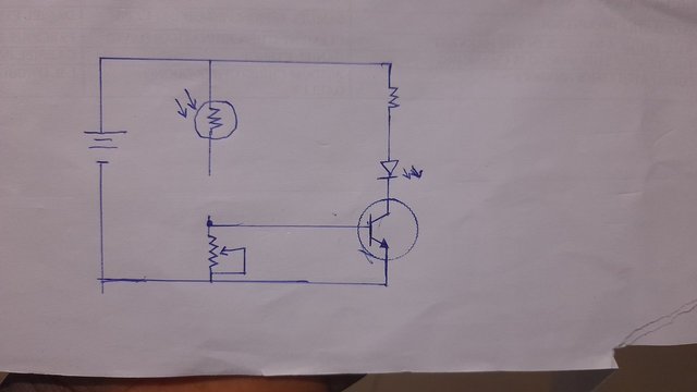
Image from @ubongudofot
Circuit 1 has:
- Battery
- Light dependent resistor
- Variable resistor
- Transistor
- LED
- Resistor
The circuit is connected to all the components with with a jumper wire but there's a break in the connection with will make the circuit dead. The wire with the light dependent resistor is not joined to that with the variable resistor. It's is an open circuit
Circuit 2
Circuit 2 have the same components as circuit 1. Difference is circuit 2 is completely connected and can emit light to the LED and the LDR can make use of light present. It is a close circuit
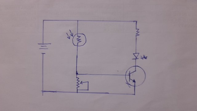
Image from @ubongudofot
Task 4:
Draw any complete simple circuit of your choice using some components we introduced in week 1, state it's function.
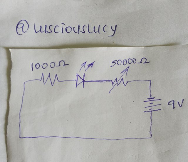
Components I used:
- Resistor of 1000Ω
- LED
- variable resistor of 5000Ω
- Battery of 9v
Function
The function of this circuit is to emit light from the LED and allows control of the light.
The resistor balance the energy and the variable resistor allows to control the bright of the light from the LED.
Task 5:
Assuming 4 resistors are connected in series and they are: (Brown black black Gold), (Brown black brown silver), (Red black black gold), (Brown green red gold), what are those resistors?
Brown black black gold
(Brown= 1, Black= 0, Gold 5%)
=10Ω (black with one zero cannot be a multiplier)Brown black brown silver
(Brown= 1, Black= 0, silver 10%)
=10 x 10= 100ΩRed black black gold
(Red= 2, Black= 0, Gold 5%)
=20Ω (black with one zero cannot be a multiplier)Brown green red gold
(Brown= 1, Green= 5, Red= 2, Gold 5%)
=15 x 100= 1500Ω
Since they are connected in series, (10+100+20+1500)Ω = 1,630Ω
Conclusion
This week teaching has made me realize how interesting electronics is. With proper understanding and mentoring. The class was so detailed. Building circuits feels like having the opportunity to create things.
Saludos alumna @lusciouslucy la he visto participar en 2 Lecciones y eso lo aprecio mucho porque estás demostrando interés en aprender algo que sabemos que no es fácil o atractivo para otros Steemians.
Valoro tu esfuerzo, quizás tengas fallas, pero sigues perseverante. Espero verte en la lección 4.
Tiene teoría y con el multimetro que utilizas puedes hacer la práctica, verás que se te hará interesante comprobar el estado de un transistor.
Éxito.
Downvoting a post can decrease pending rewards and make it less visible. Common reasons:
Submit
Downvoting a post can decrease pending rewards and make it less visible. Common reasons:
Submit
Esa es la actitud de los ganadores, aprender de los errores e ir mejorando, pero sin dejar de intentarlo.
Downvoting a post can decrease pending rewards and make it less visible. Common reasons:
Submit