Hello physicists, electricians, and electrical engineers in the making
Defination of an electric circuits
An electric circuits in never a word that can stand on it own without other component making it up, the pathway which current is know to flow is an electric circuit and the components that comprises it are a battery which is a source of power, a conductor mostly used is a wire of different types, dimension, length, a resistor one that hinder the flow of current or is responsive to the current passed through it and that could be a bulb, something that generates heat, a resistor doesn't neccesary has to be an appliance that give out heat, but energy that flows through most of this resistors are converted to heat reducing the current flown, switches or what is called a key in physics, a capacitor and inductor, this are always found in a broader and complicated circuit not simply one's.
As explained in the courses, this circuit has a way and pattern in which a component is connected, and so far, with my little elementary knowledge of physics in secondary school, I was told that a resistor and capacitor can be connected either in a parallel or series form.
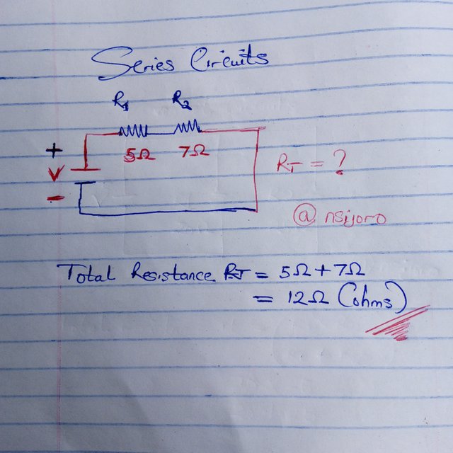
Series circuits: As the name implies, the components are connected one after the other in a straight line.
Parallel circuits: In this circuit, each component connection overhears each other.
In advanced circuit connections, most of our appliances have both connections (combined) and hidden in their motherboards.
Importances of an electric circuit
Without an electrical circuit, there is no electrical product.
Transmission and distribution of power wouldn't have been possible without an electrical circuit.
It is the circuit that controls the electrical system because each component mentioned in the electronic circuits above we cannot do without; you will never see an appliance without a power on and off initiation button (the key or switch).
It ensures safety; the arrangement of the resistor and conductor in the circuit is done in such a way that it prevents electric shocks and easy fire outbreaks even with an elongated time of usage.
A well-designed circuit reduces energy loss and energy consumption from the battery.
Difference between the series and parallel circuits
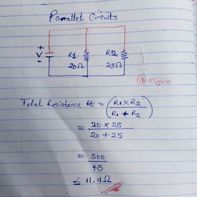
The first difference I can point out is the formula difference of the series and parallel circuits, which is in the image below.
Parallel Formula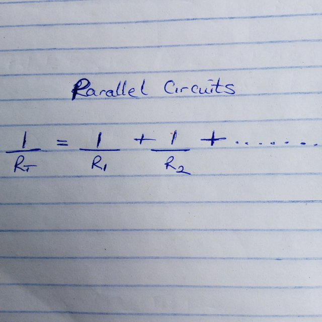 | Series Formula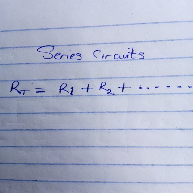 |
|---|
Another difference is their connection pattern or component connection. Components are connected end to end in a series circuit, while in a parallel circuit, the components are connected overhead between the same node, and this makes the same voltage run through it.
Note the above two circuits and mention their names, and calculate the total resistance of the two circuit. Assume any value of R1 and R2 but not the value specified in the course.
Wire Connection Steps
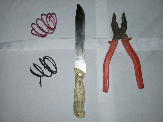
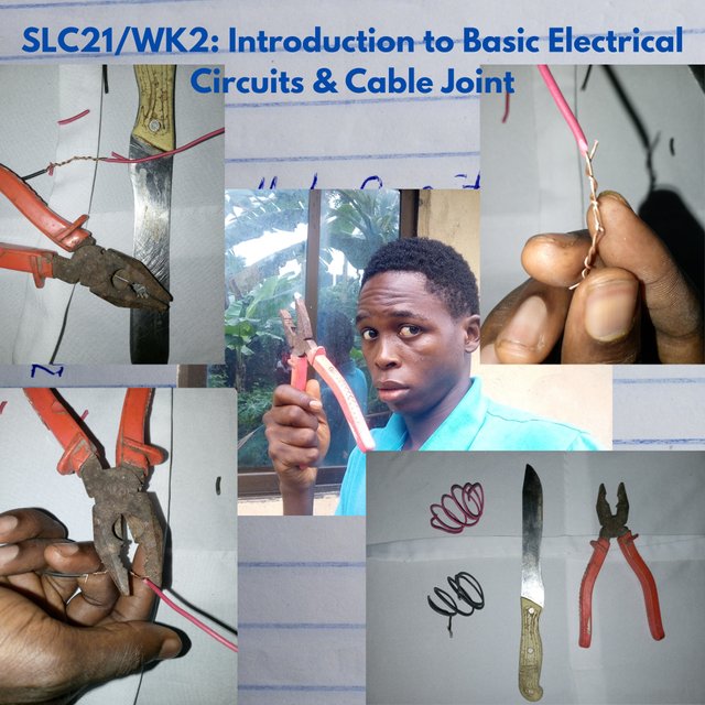
- I picked my wires from my toolbox and unrolled them. I chose a distinctive colour so that I can note the differences while connecting.
 ✅ ✅ |  ❌ ❌ |
|---|
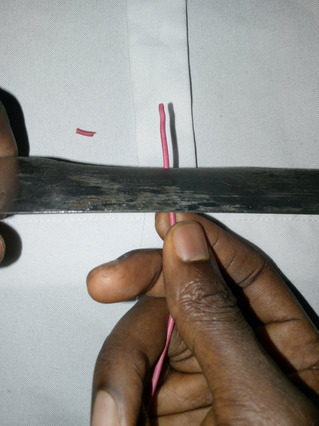
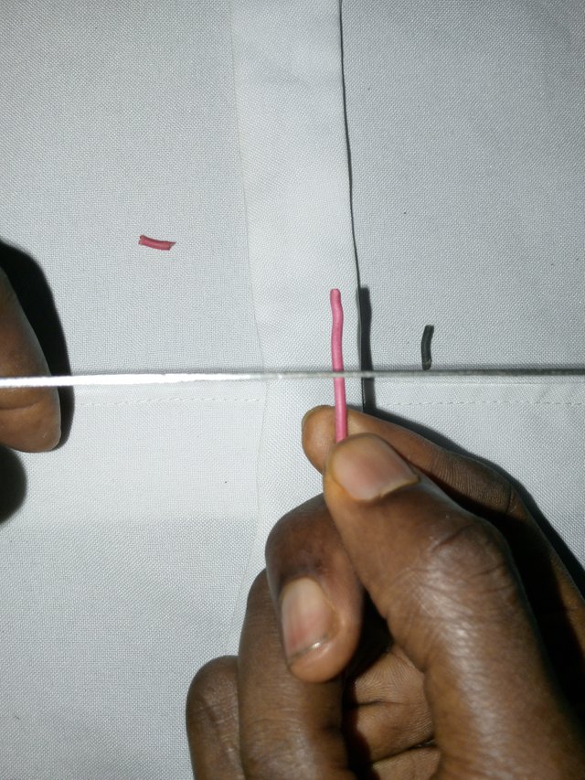
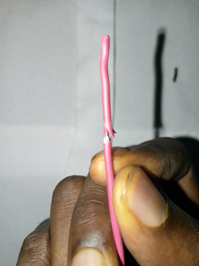
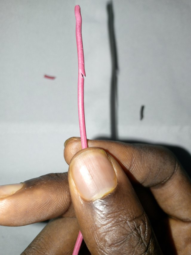
- I place my knife in a degree lower than 90°, as we all know that a 90° placement will damage the insulation.
 |  |
|---|
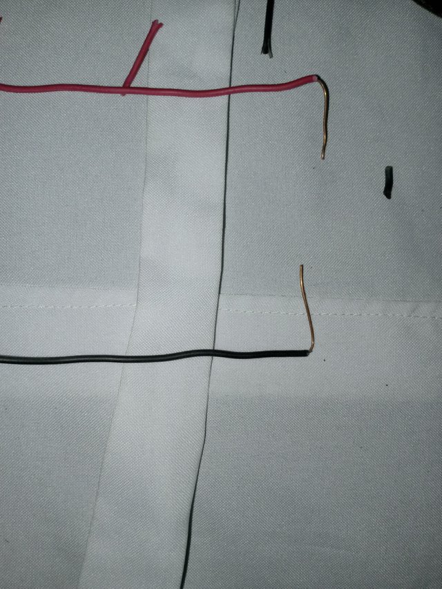
- I cut the insulation in four angles while my knife was still maintaining the 60° position, then I turned the back edge of my knife and the insulation out. A tip of a plier can also be used, but I preferred the knife's back edge.
 |  |  |
|---|
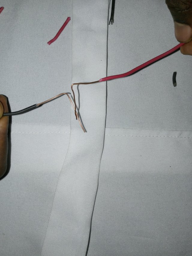
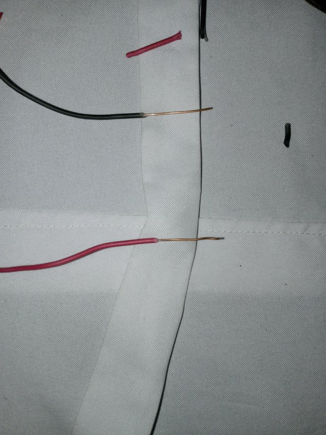
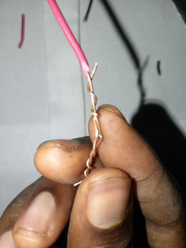
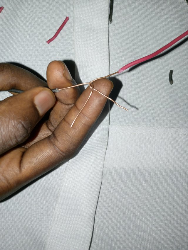
- After pulling it out, I bent the naked conductor to 90 degrees, and then I crossed it over the other bent the same way.
 |  |
|---|
- I twisted each of them on their own body to make the wire strong. The wire I used was a very strong one, so I had to use my pliers to complete the twist slowly, and it was done.
My lessons so far

I have learnt so much from this lesson. Initially, I knew about the type of circuits, their connection pattern, and their calculation since I graduated from the science class and had an A1 in physics, but the step to the connection of wires, I never knew them, so I am so thrilled to see processes like skinning and scraping, though it is a common term, but I never knew it was applicably used in this field of electricity...
I would love @ubongudofot @basil20 and @whizzbro4eva to join in this contest
I learned a lot from reading your post, especially its attachment and connection process. The practical part is really commendable. Thanks for such a nice presentation. Good luck for the contest.
Downvoting a post can decrease pending rewards and make it less visible. Common reasons:
Submit
Thank you so much sir
Downvoting a post can decrease pending rewards and make it less visible. Common reasons:
Submit
X promotion link
https://x.com/nsijoro/status/1854677482273747133?t=-JCBUH5ue1dAEXwa0DQq-w&s=19
Downvoting a post can decrease pending rewards and make it less visible. Common reasons:
Submit