 Snapped with Nokia C30

A circuit diagram is a specific arrangement of Electronic components that performed a predicted function. circuit building is the process of bringing a circuit to life by assembling it as indicated in the circuit diagram. And this is what this week's workshop is about.
Task 1: Circuit Building.
Showing the how to build the circuits in figure 1 and figure 2
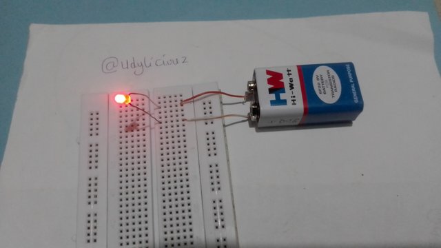
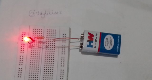
Building figure 1
 @
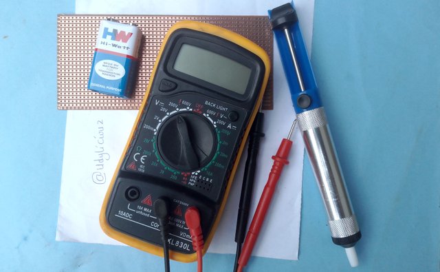
@Components needed for building figure 1 are:
- Breadboard
- LED diode
- 9 volt battery
- Jumper cables
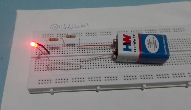
Building figure 2
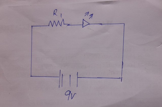 @
@Components needed for building figure 2 are:
- Breadboard
- 1k Resistor
- LED diode
- 9 volt battery
- Jumper cables
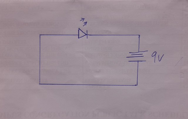
Task 2: Circuit Diagram.
Drawing a circuit diagram of a LED attached to 2 resistors of 1k ohms connected in series and powered with a 9V battery.
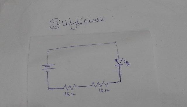
Steps taken when drawing this
I had to make sure all the important components are represented in the circulatory.
- Starting with the battery at the left,
- I connected a line to the first and second resistor,
- and finally the LED diode.
- continue the line back to the battery.
The two resistors made a combined resistance high enough to make the LED bulb dull.
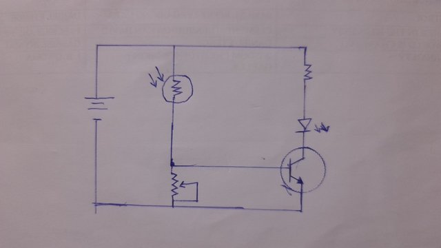
Task 3: Circuit interpretation.
Circuit 1
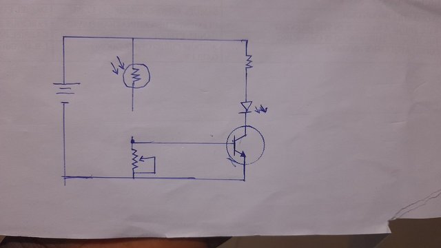 @
@This circuit uses DC from a battery to light a LED bulb, the LED bulb is protected by the resistor close to it. The connection passes through a transistor that will act as switch controlled by a veritable resistor.
Circuit 2
 @
@Circuit 2 resemble circuit 1 but with an important difference, This circuit also uses a DC power from a battery to light a LED bulb, the LED bulb is also protected by the resistor close to it. The connection passes through a transistor that will be acting as switch controlled by a veritable resistor and a photo-resistor. Circuit 2 is automatic and can be controlled by light around it.
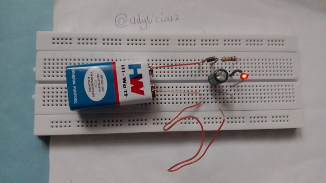
Task 4: my Circuit.
Powering LED bulb with a capacitor
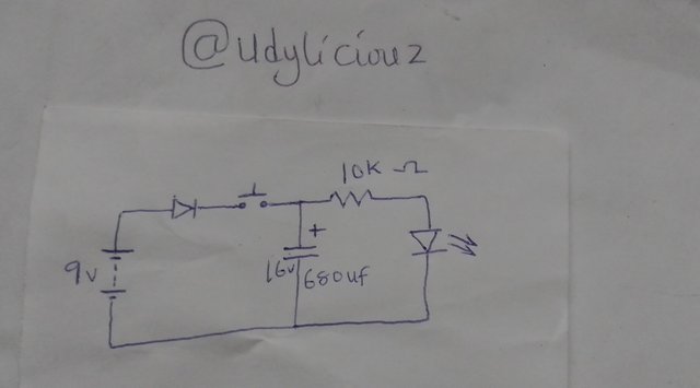
Each time the switch is taped, the 9 volt battery charges the 680uf capacitor and the capacitor keeps the LED bulb on for some time before it goes off.
The 10k resistor protects the LED bulb.
The Diode protects the circuit.
I tried it and it worked, the LED bulb is on for some time after the battery is disconnected.
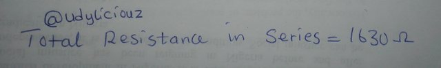
Task 5: Resistor colour codes
Assuming 4 resistors are connected in series and they are:
Brown black black Gold

Brown black brown silver

Red black black gold

Brown green red gold

what are those 4 resistors are connected in series?
Thank you for creating this opportunity to expand in my appreciation for electronics, once you understand this tiny things, they become very interesting to spend time with. Looking forward to learning more.
I am inviting @jozzie90 and @johnmitchel and @simonnwigwe
Here is the link to the assignment
https://steemit.com/hive-188837/@ubongudofot/s19-wk3-interpretation-of-circuit-diagram-circuit-building
Thank you, friend!


I'm @steem.history, who is steem witness.
Thank you for witnessvoting for me.
please click it!
(Go to https://steemit.com/~witnesses and type fbslo at the bottom of the page)
The weight is reduced because of the lack of Voting Power. If you vote for me as a witness, you can get my little vote.
Downvoting a post can decrease pending rewards and make it less visible. Common reasons:
Submit
Upvoted. Thank You for sending some of your rewards to @null. It will make Steem stronger.
Downvoting a post can decrease pending rewards and make it less visible. Common reasons:
Submit
Hola amigo que bueno ver que te hayas esforzado en esta 3era semana felicitaciones por ese gran trabajo
Saludos
Downvoting a post can decrease pending rewards and make it less visible. Common reasons:
Submit