Hello friends, I'm delighted to be one of the participant of this week learning challenge titled adder Diagram PLC Programming and Solar Power. Believe it was an impact class, below I'm expected to exercise on the task give.
Without further ado...
| Task 1: |
|---|
A. What is meant by ladder diagram PLC programming? Draw a ladder diagram and explain.
| Answer... |
|---|
According to this week class, a ladder diagram is a PLC program that can converts electrical wiring into machine language wiring, the symbol is used to convert electrical wiring with some ladder logic.
The Ladder diagrams basically aimed to facilitate human to use of PLCs by programming electrical signals, it represents the control logic in a format resembling an electrical schematic of relay logic, The name is derived base on it resemblance to a ladder with two vertical rails and several horizontal rungs when representing it on diagram.
Rails: those vertical lines stand for the power supply and one of it is the active or hot line and the other is the neutral or return line.
Rungs: those horizontal lines stand for control logic, Each rung clear describe a specific operation.
Logic symbols: the standard symbols like the contacts inputs, coils which is the outputs and functions that is the ***timers, counters and others are also used.
Execution: it is of normal circumstance that any PLCs execute their ladder diagrams from top to bottom which evaluates conditions on every rung presented.
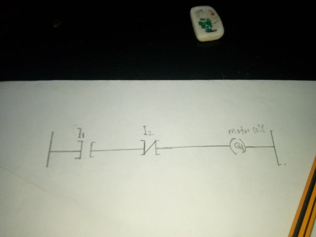 My Diagram Explanation
The start Button (I1): when it is being pressed the NO contact will closes and gives the coil (Q1) energy and the motor starts.
Seal-In Contact (Q1): here the parallel path is created using the Q1 to maintain the motor operation after the Start button is released.
Stop Button (I2): this NC contact makes sure that the motor stops when it is being pressed, the (I2) button breaks the circuit in other to mitigate energy from the coil (Q1).
I believe my diagram showcases the simplicity and logic and nature of Ladder Diagram programming in PLCs from what I have learned so far.
| Task 2: |
|---|
Write the work by drawing the symbols of the input and output elements of the ladder diagram.
| Answer... |
|---|
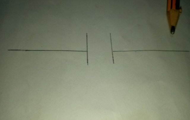
Normally Open (NO) Contact
The Normally Open (NO) contact describe a type of electrical contact that is open which is not conducting when the input is not energized, then when the input is being energized the contact will closes allowing current to flow, my below diagram is the symbol of the Open contact.
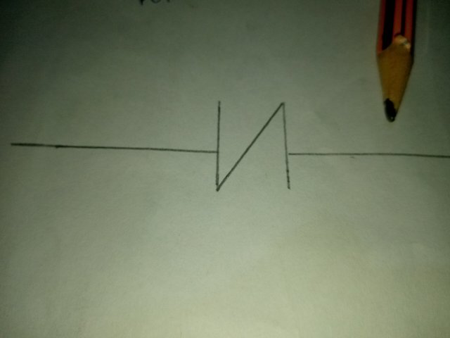
Normally Closed (NC) Contact
The Normally Closed (NC) contact describe a type of electrical contact that is closed which is conducting when the input is not supplied with energy, when the input is being energized the contact opens resulting in breaking the circuit
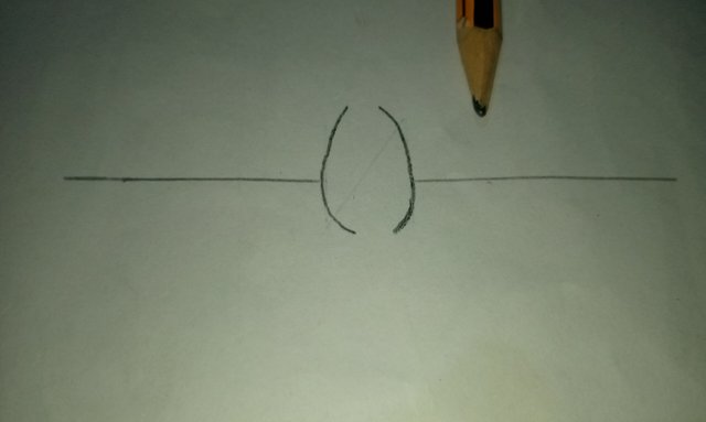
Coil
The coil is an output device which represents a load like the a motor, valve or lamp When the coil is being energized the load will turned on
| Task 3: |
|---|
Draw the ladder diagram with three input ladder logic gates (AND, OR) and explain with practicals.
[With symbols and truth tables]
| Answer... |
|---|
Here to create a ladder diagram that have the AND and OR logic gates with three inputs I am going to work on the below to demonstrate.
• The AND Logic Gate in Ladder Diagram
• The OR Logic Gate in Ladder Diagram
• Also the Truth Tables for each logic gate.
Starting with
1. AND Gate in Ladder Diagram |
|---|
Logic: in the below diagram the output is ON only when all inputs are ON
Ladder Diagram for AND Gate:
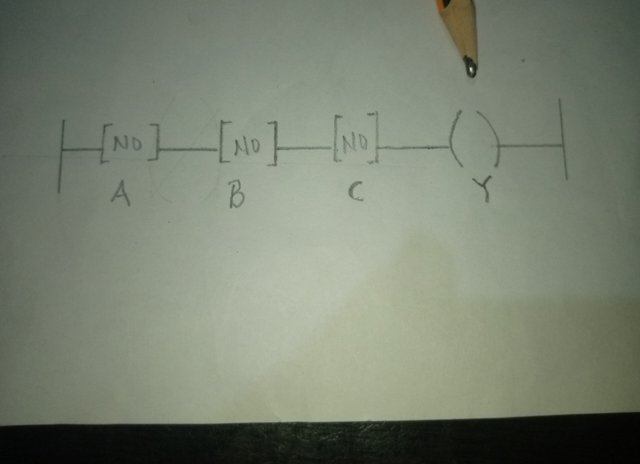
The Inputs: A, B and C (NO Normally Open contacts)
The Output: in my diagram represented as Y the (Coil)
It Condition: All switches A, B and C must be closed (ON) before the output Y can turn to ON.
| Input A | Input B | Input C | Output (Y) |
|---|---|---|---|
| 0 | 0 | 0 | 0 |
| 0 | 0 | 1 | 0 |
| 0 | 1 | 0 | 0 |
| 0 | 1 | 1 | 0 |
| 1 | 0 | 0 | 0 |
| 1 | 0 | 1 | 0 |
| 1 | 1 | 0 | 0 |
| 1 | 1 | 1 | 1 |
2. OR Gate in Ladder Diagram |
|---|
The Logic: below shows that the output is ON when any one of the inputs is ON.
Ladder Diagram for OR Gate:
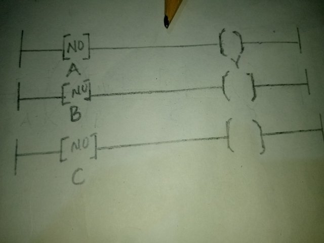
The Inputs: A, B and C (NO Normally Open contacts in parallel)
The Output: in my diagram represented as Y (Coil)
It Condition: If any one of the switches A, B or C is being closed (ON) the output Y is going to turn ON.
| Input A | Input B | Input C | Output (Y) |
|---|---|---|---|
| 0 | 0 | 0 | 0 |
| 0 | 0 | 1 | 1 |
| 0 | 1 | 0 | 1 |
| 0 | 1 | 1 | 1 |
| 1 | 0 | 0 | 1 |
| 1 | 0 | 1 | 1 |
| 1 | 1 | 0 | 1 |
| 1 | 1 | 1 | 1 |
AND Gate Example
Case: using a conveyor belt for the explanation, it is know that a conveyor belt can only run only if three condition are certain
- A.. only when the safety switch is ON

- B... when the  Start button is pressed as well as the

- C... when the overload sensor is detecting detects no fault on it
My ladder diagram above ensure that all three inputs A, B and C must be ON for the conveyor motor which is represented as (Y) to start
OR Gate Example
Case, using the senerio of a warning light being turned ON if any one of the following conditions take place.
A... when high temperature is being detected

B... when high pressure is being detected

C...when emergency button is being pressed
My ladder diagram show that the light (Y) can only turn ON if any one of the mentioned inputs is being activated
| Task 4: |
|---|
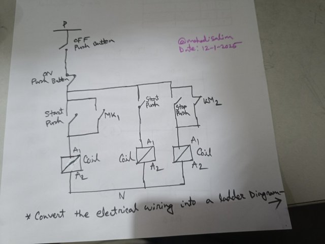
Convert the electrical wiring in the figure below into a ladder diagram.
| Answer... |
|---|
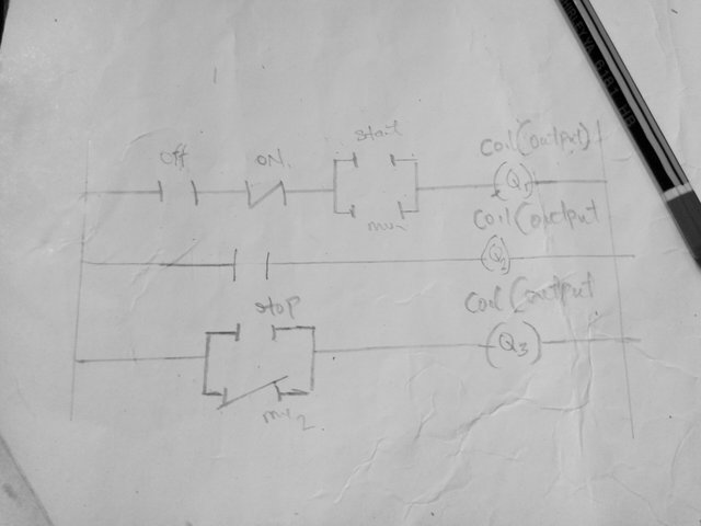
her I'm presenting a Ladder diagram and the working procedure of the power circuit through it common vertical and horizontal lines is presented in my diagram below.
Vertical Rail : the Vertical lines is dawn on the left and right sides of the diagram which indicate the direction of the power supply in the ladder.
source for Voltage : here the battery is connected in the a horizontal section to Indicatenit source
There we also have the NO, NC and the coil presented
| Task 5: |
|---|
Solar power is generated in your home with three 12-volt 100 AH batteries. An additional 12-volt 100 AH battery needs to be connected as your home's electrical load increases. Explain the series and parallel connection of four batteries with diagrams.
[Note: Practical can be done with multiple batteries of any rating.]
| Answer... |
|---|
Now in this task E to explain how to connect four 12-volt, 100 AH batteries in the series and parallel
let me first clarify the concepts and the practical implications of the connections before my diagram
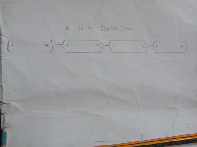
In the series connection the positive terminal of one battery is connected to the negative terminal of the next battery, by this method of connection increases the voltage and keepthe ampere hour (AH) capacity to remain constant
Practical Example
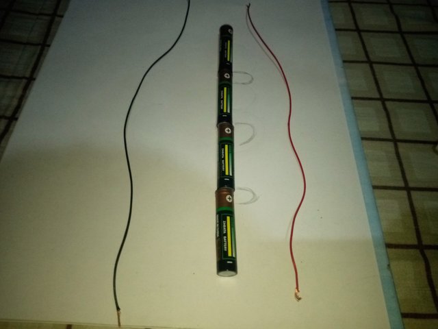 clearly illustrate the series connection
Connect Battery first positive terminal to Battery second negative terminal
Connect Battery the first positive terminal to Battery third negative terminal
Connect the third battery positive terminal to Battery the fourth negative terminal
The Total Voltage=12v+12v+12v+12v
= 48 volts✅
The Total Capacity :- = 100 AH✅
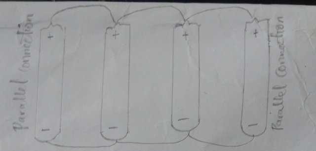
Now in parallel connection all positive terminals need to be connected together and all negative terminals are to connected together too, this method of connection increases the ampere hour (AH) capacity and keep the voltage constant
Practical Example
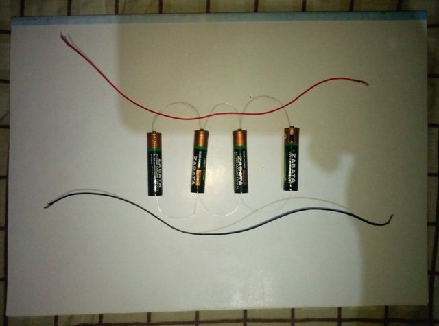 clear illustrate the parallel connection
Here is expected to connect all positive terminals of those batteries together
And is expected to connect all negative terminals of the batteries together too
The total Voltage = 12 volts
The total Capacity = 100 AH + 100 AH + 100 AH + 100 AH
=400 AH✅
Thanks you all for reading my entry, I won't learn alone here I'm going to invite @presh001, @samuelnkenta and @manuelhooks to participate in this learning challenge. I'll be looking forward to reading your entry thanks.

