Hello everyone,
I am going to be sharing with you step by step tutorial on how to create a gear from scratch and also show you how a gear will make another gear move when they meet.
The software required is AUTO-DESK FUSION360
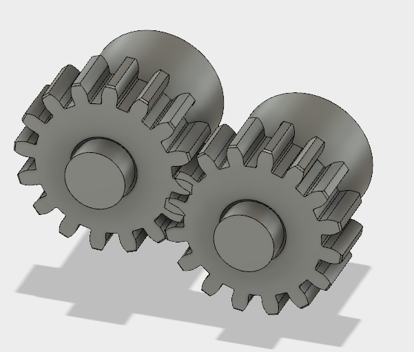
This is what we plan achieving in the video below
AUTO-DESK FUSION360 is a software for several designs that helps everyone prepare for the future of design. It is used for Modelling, Patching, Rendering, Animating, Simulating and Drawing of a polygon also known as an object.
Using FUSION360, there are many ways in which a gear can be designed and I am sharing two out of all the ways one can design a gear and I will try as much as possible to make all work very easy so that anyone that is not used to this software can understand.
METHOD 1 ; MODELLING A GEAR FROM SCRATCH.
Before we proceed, I will love to show some important things one need to understand.
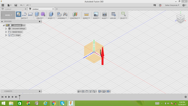
Creating a new page on fusion360 looks like the below image
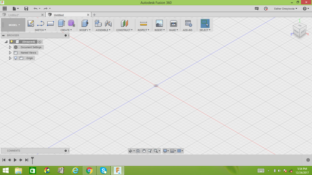
It is always easier to work in 2D, one has to create a sketch so you can work with any of the 2D worksheet and I usually go for XY axis.
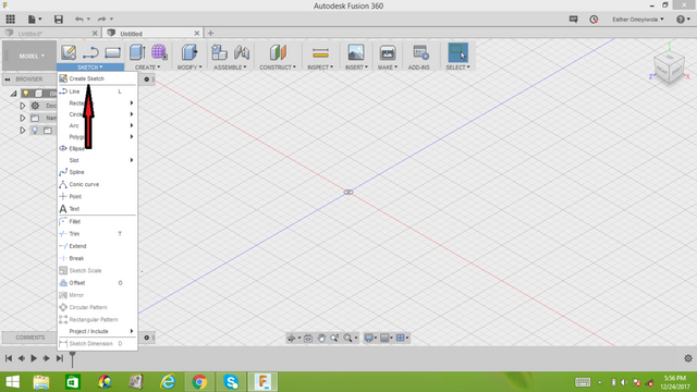
We are going to begin by sketching a circle
NOTE; pressing the 'c' key on your keyboard activates the centre circle tool.
Use the 'esc' key to delete
STEP 1
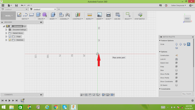
Press key 'c' on your keyboard and place the center point of your arrow at the middle of your working sheet to make it the center of your circle. You can actually pick any other point if you wish, but I usually go with the center of my working sheet.
STEP 2
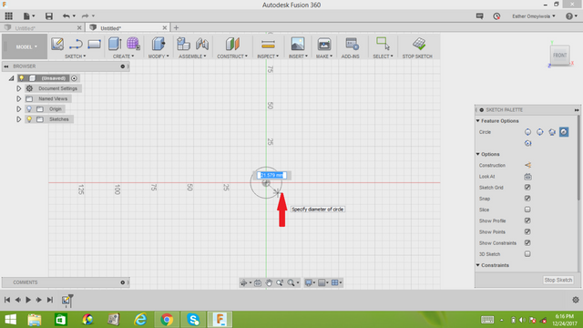
After picking a point, drag the pointer away from the center of your circle you picked to construct a circle
STEP 3
Depending on the diameter of circle you want, you can easily specify the diameter in the box as seen below.
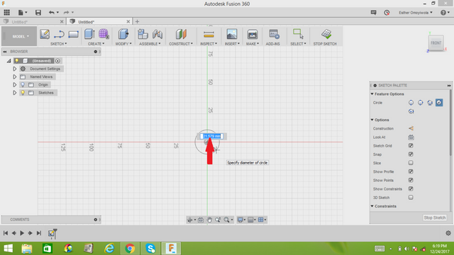
I am working with diameter 40mm, so I specify and left click on my mouse.
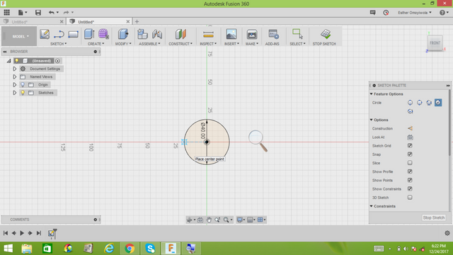
STEP 4
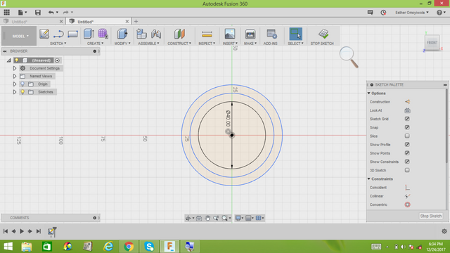
We are going to be using 3 circles for the modelling of a gear and we have successfully created a circle with diameter 40mm in step 3. Two more circles will be created with diameter 50mm and 60mm respectively.
Do not forget to activate your circle mode by pressing 'c' key on your keyboard using the same center point as that of the first circle.
Your three circles should appear like this
STEP 5
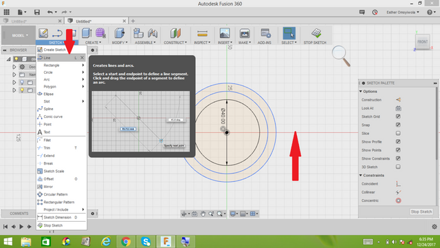
We want to define the teeth angle of the gear.
Make the horizontal axis of your working sheet as the reference axis.
Click on sketch an select line
STEP 6
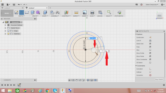
Make a line from the center of the circle to the outermost circle. Before leaving the cursor at the end point, press tab and enter 10 deg then click enter, you can use any degree. I chose 10 degrees.
STEP 7
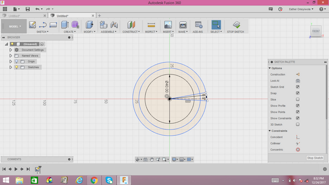
We are creating three different lines of different degrees as done in step 6 above. Apart from the 10 deg I picked, I will be using 6 deg and 3 deg for the other 2 lines.
Your lines should look like this
STEP 8
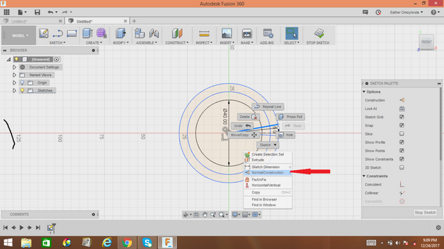
Convert the 3 lines drawn which is referred to as SKETCH LINE to CONSTRUCTION LINES. Click on the first line, right click on the line and select 'normal or construction' option then the first line turns into a dashed line.
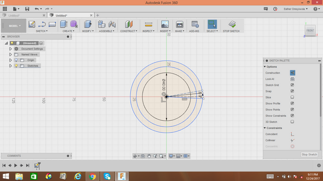
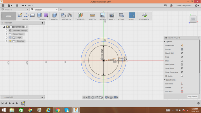
Repeat for the other two angle lines and be sure to see dashed lines
STEP 9
Sketch on the 10 deg line from the center point of the circle to the innermost edge of the circle. Remember sketch, select line.
As seen below, the sketched lines have turned blue closing some dashes.
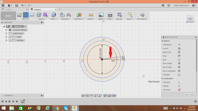
From the end point of the 10 deg line, connect on the second degree line from the edge of innermost circle to the edge of outer most circle with a line as done as above.
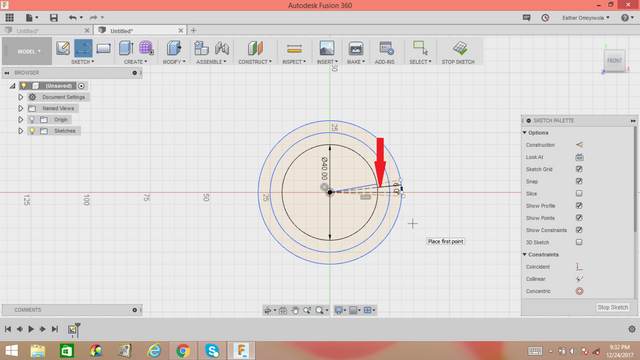
For the last line, connect with a line from the middle of the circle to the outermost part of the circle.
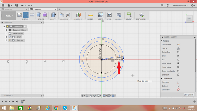
STEP 10
Click on sketch, select arc and select 3 point arc. We want to make an arc between the second circle and the outermost circle. To give it a curve, move your mouse around and click till you get your desired curve.
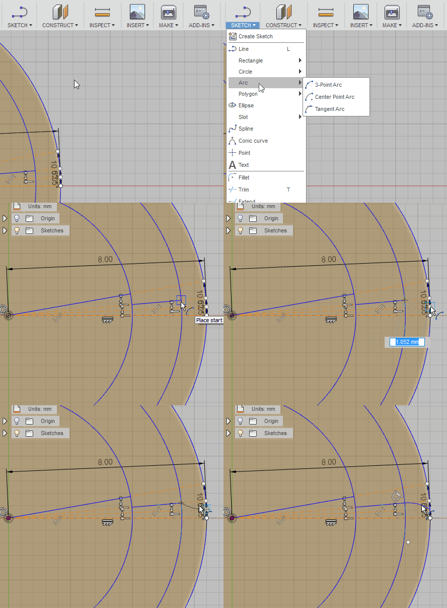
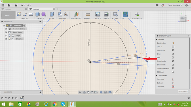
click on the sketch and select line to close the little space between the curve and the outermost circle.
STEP 11
Highlight your sketch by clicking down 'ctrl' key and select the faces of the sketch.
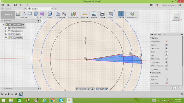
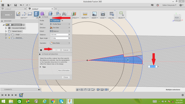
Once highlighted, right click and select press pull, an extrude page comes up. Inserting any distance is to make the object extrude with some thickness. I used 4mm then click enter.
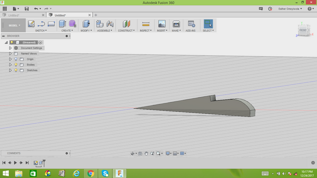
STEP 12
Selecting 'f' key on your keyboard activate FILLET. Select the edge and pull it out. I am making a fillet of 0.20mm. Select the point as seen below and enter 0.20mm or used another radius.
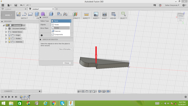
STEP 13
Mirror the image by clicking on create at the top of your working sheet and select mirror. Make sure you select bodies as your pattern type.
Click on the body of the object and select mirror plane.
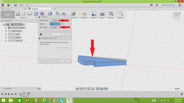
Three axis will show up, select the axis that would give the object a mirror image of itself.
Then the half image doubles facing each other.
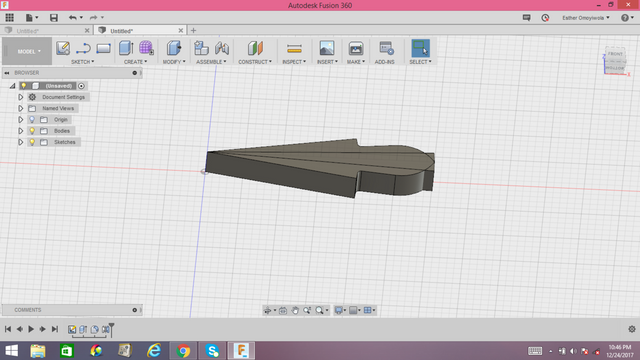
FINALLY
Combine the half teeth.
Go to modify, select modify and select the the two bodies and click ok. They are finally joined.
Go to create, select pattern, click on circular pattern. select bodies as pattern type then click the object.
Click axis and select the middle of the object axis, input the number of teeth you require and click enter.
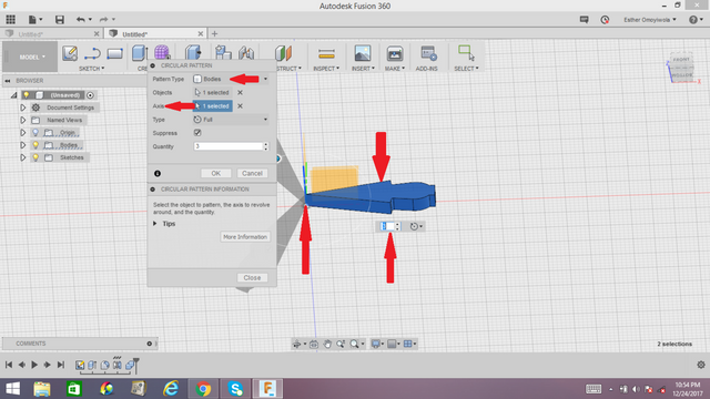
Finally your gear appears. How does it look? With these understanding, you can keep practicing till you are perfect and try other designs to work on.
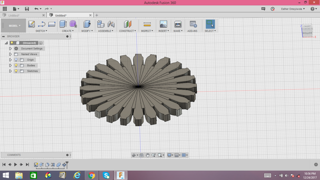
SECOND METHOD OF CREATING A GEAR
IMPORTING FROM McMaster CATALOG
STEP 1
Click on the insert and click and select 'insert the McMaster -carr component.
One important thing you should know is that creating gear from this method simply needs one to be connected to the internet.
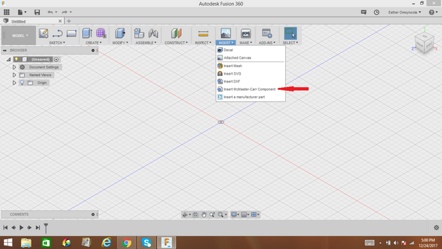
STEP 2
This will take you to mc master catalog where you can search for anything. Now, as we know we are about gear, click the search icon to search for gear. variety of options come out, select the 'standard gear' and you see different kinds of available gear.
STEP 3
Pick the gear with 'metal gears- pressure angle' and it will take you to where you get to choose the particular gear type you want. I picked the first gear type which is '6325k89', you could try to pick another gear type after this tutorial.
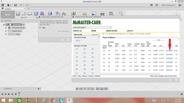
STEP 4
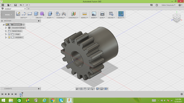
Click on product details and scroll down till you find a 3-D solid works box. Click on the drop box icon and a list will show and then select 3-D STEP and click save.
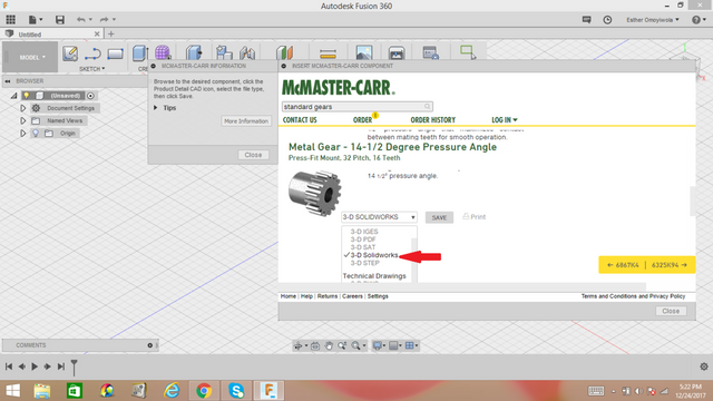
It will automatically bring the 3-D model on your current work space.
STEP 5
Draw out the gear shaft cross section by pressing the 'c' key on your keyboard to create a circle.
Select the circle you just created. Selecting the E key on your keyboard automatically activate extrude action. Click on the direction and select symmetric.
Click on the operation and select new body
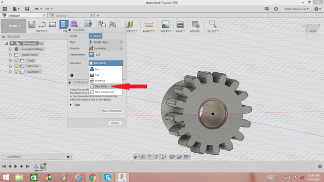
Click on the face of the shaft and enter the distance you want your extrusion to be from the main gear. I used 2mm
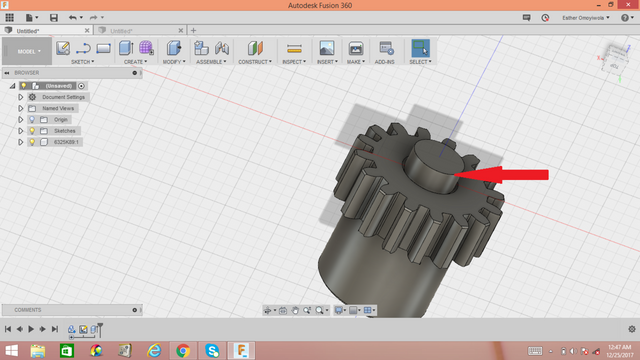
STEP 6
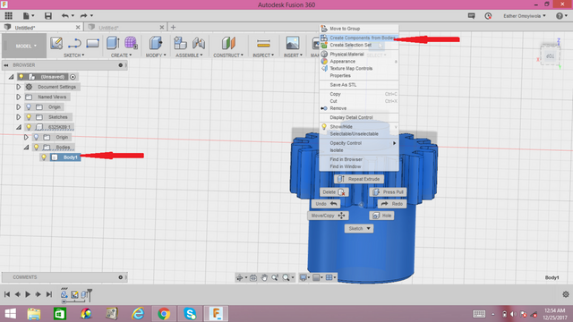
Go to bodies on the left part of your working sheet and click body 1, the right click on the object and click 'create component from bodies' and you will notice that after doing this, the body section on the left side vanishes and a new component appears.
STEP 7
Duplicate the component by by selecting the gear and shaft and right click to select the 'move/copy' option.
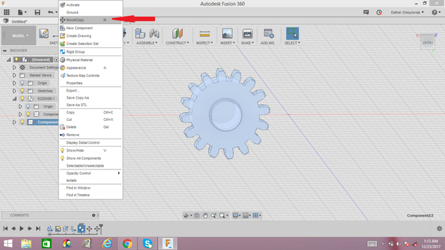
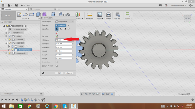
Another box comes out. Make sure the component are selected and make sure you set pivot. Moving the component in the in the x axis, input a value till you arrived at the perfect separation of the two gears.
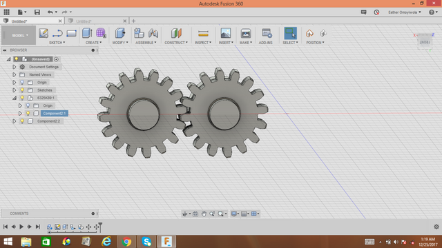
STEP 8
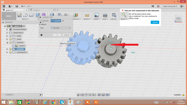
Go to ASSEMBLE up our worksheet area, click on 'as built joint' option,click on 'revote'. For the first gear, select the gear first and the shaft next so that the gear can rotate around the shaft and select the position around which it will rotate.
Repeat same for gear 2
FINALLY
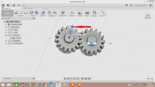
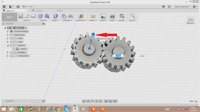
To rotate the gears double tap the position flag of the main gear and this will show up. Then with your mouse, you can start moving the two gears around in whatever degree you want.
CONCLUSION
On taking note of these steps, you have successfully created a gear and learnt two methods in which you can model a gear. I do hope you enjoyed every bit of this tutorial. Start trying out lot of designs with AUTO-DESK FUSION360.
NOTE; ALL IMAGES AND VIDEO USED ARE ORIGINALLY MINE, ALL DEFINITIONS USED ARE FROM MY EXPERIENCE SO FAR ON THIS SOFTWARE AND OTHERS.
THANKS FOR LEARNING. IF YOU HAVE ANY QUESTION, FEEL FREE TO ASK IN THE COMMENT BELOW.
Wow, i can't believe this much hard work was from a lady, no hard feelings but i am extremely amazed by this tutorial, i am a 3d animator but i am only used to the maya software, the fusion 360 is a very complex one, but you just broke it down like it's nothing, this is a nice one heart God bless you.
Downvoting a post can decrease pending rewards and make it less visible. Common reasons:
Submit
lol dude women are every bit as smart and hard working as men... and often, more, because they have to overcome stereotypes that guys hold...
Downvoting a post can decrease pending rewards and make it less visible. Common reasons:
Submit
I am really impressed with this post @goldenheart! I know how long it takes to do a detailed tutorial post like this, having done a few myself. Your screencaps illustrate the process very clearly and I love the gif and video - all in all, a really awesome post that explains just enough of the software as you are progressing to keep the reader well informed, without being overwhelmed. I am happy to follow you and looking forward to more posting from you. Cheers - Carl
Downvoting a post can decrease pending rewards and make it less visible. Common reasons:
Submit
Thanks @carlgnash.
Downvoting a post can decrease pending rewards and make it less visible. Common reasons:
Submit