Hi ! I received my pack of 5 "TB6600" Stepper Drivers for the 3DPrinter. They are quiet cheap around 30 € for the set shipping included.
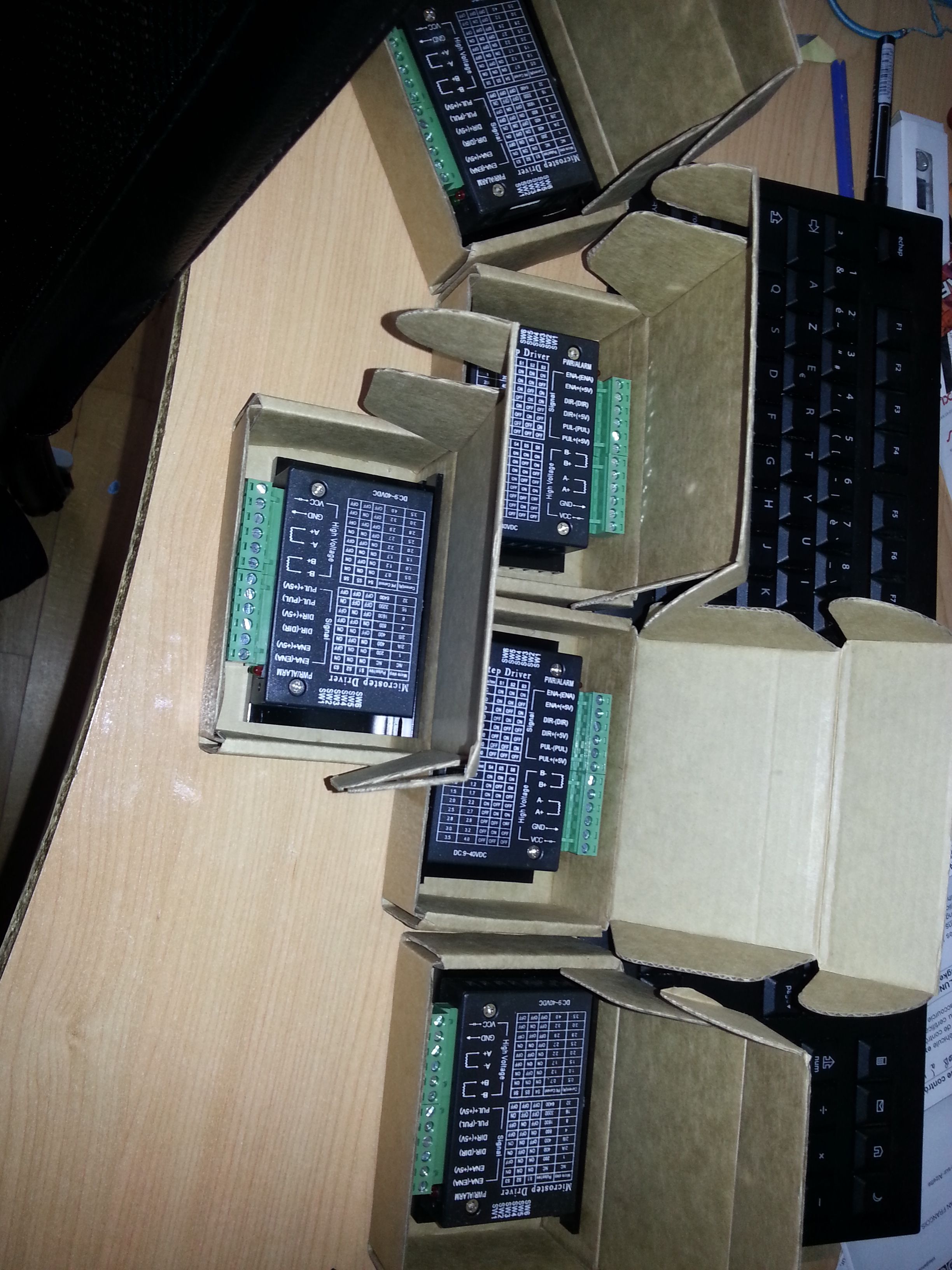
I took the time to check each one: PCB, assembly, connectors and so on.
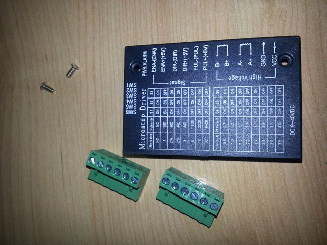
There are just two screws to remove on the top and remove the connectors.
Connectors are of a good quality which is a good sign. On many 3D Printers the quality of such connectors is not good and they put some hot glue.
Next comes the PCB:
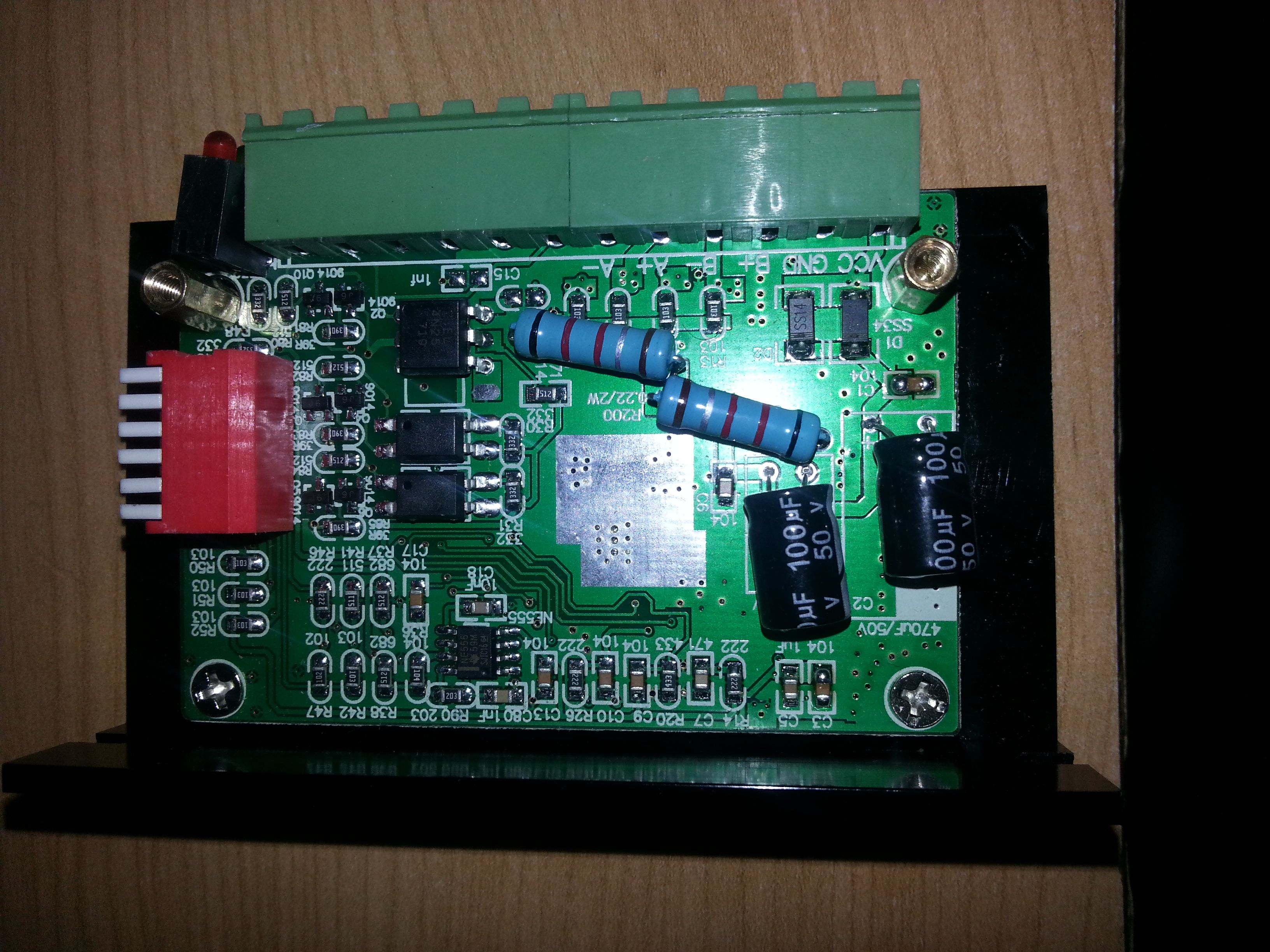
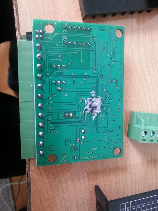
The quality is quiet ok on all of the 5, there is at least some thermal paste. It would have been better for thermals to put the radiator on the other side of the PCB.
First joke: those are TB67S109 and not TB6600 (but I expected that), rated up to 50V/4A that is why also there is 32 microstepping. Follows the datasheet http://toshiba.semicon-storage.com/ap-en/product/linear/motordriver/detail.TB67S109AFTG.html.
Now there is a second nice joke, there is a capacitor of 100 µF/50V at the power supply instead of a 470µF/50V. This is something quiet common on such TB6600 stepper drivers. I have 4 of the PCBs with a 100 µF and one with a 330 µF
There are also 2 components that are not populated on the PCB, should not be a big deal.
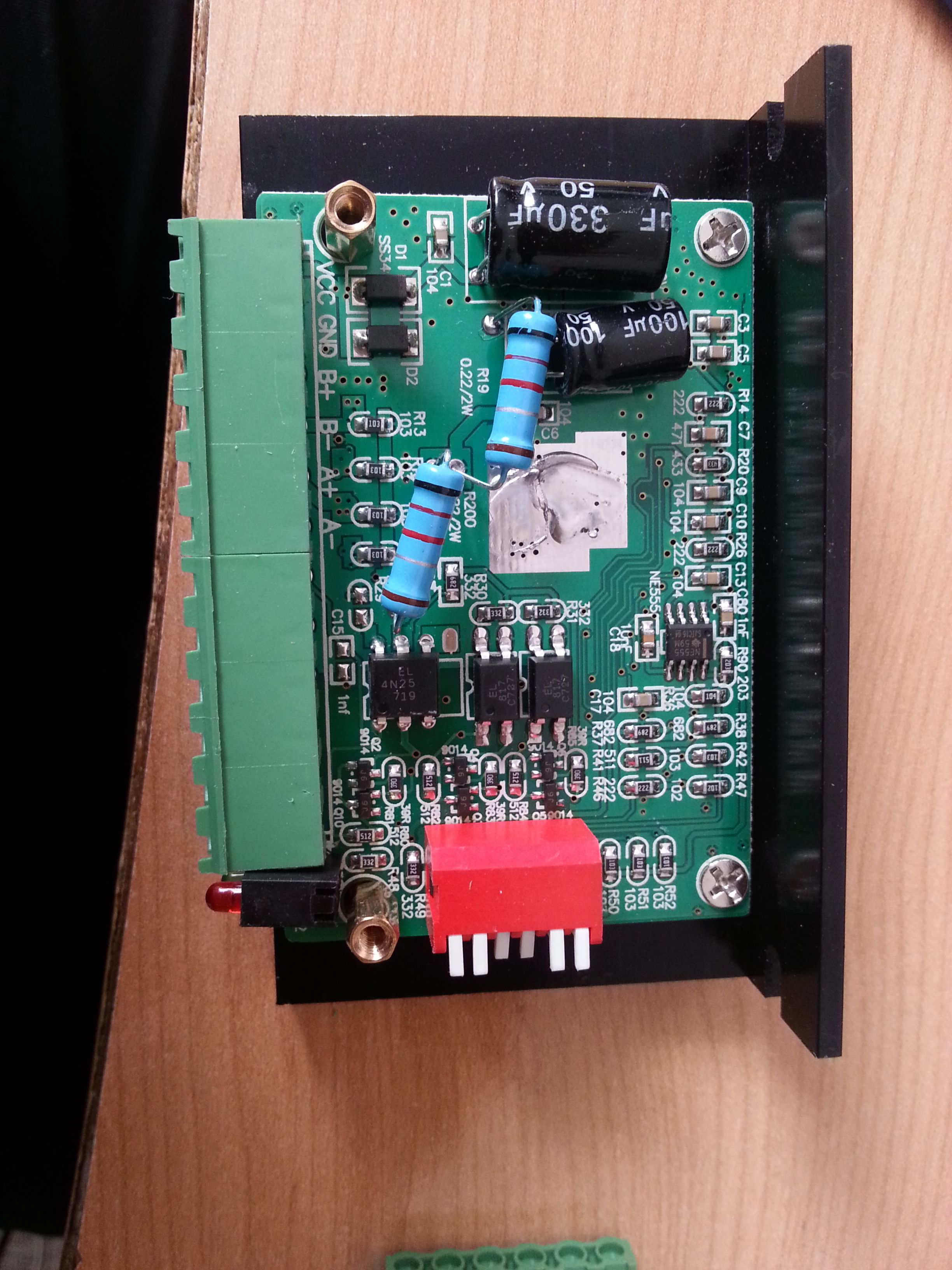
It is not big issue for those power supply capacitors, I can replace and put a 470 µF/50V. It is how they cut corners to make it super cheap.
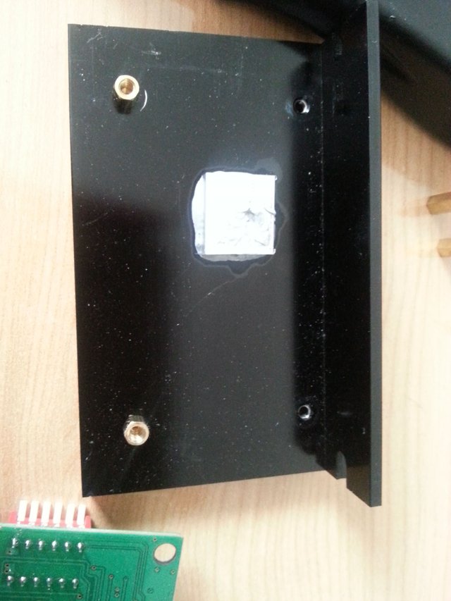
The thermal part is not terrible, I will have to fix it.
There is a small aluminium block used as interface to the IC under the PCB that seems to be glued. Sometimes, the aluminium block is not always covering entirely the IC, which is a major problem. I will have to remove it, remove the black anodization which is an insulation layer, and spend some time to have a nice polish finish before putting some good thermal paste and perform the re-assembly of the thing.
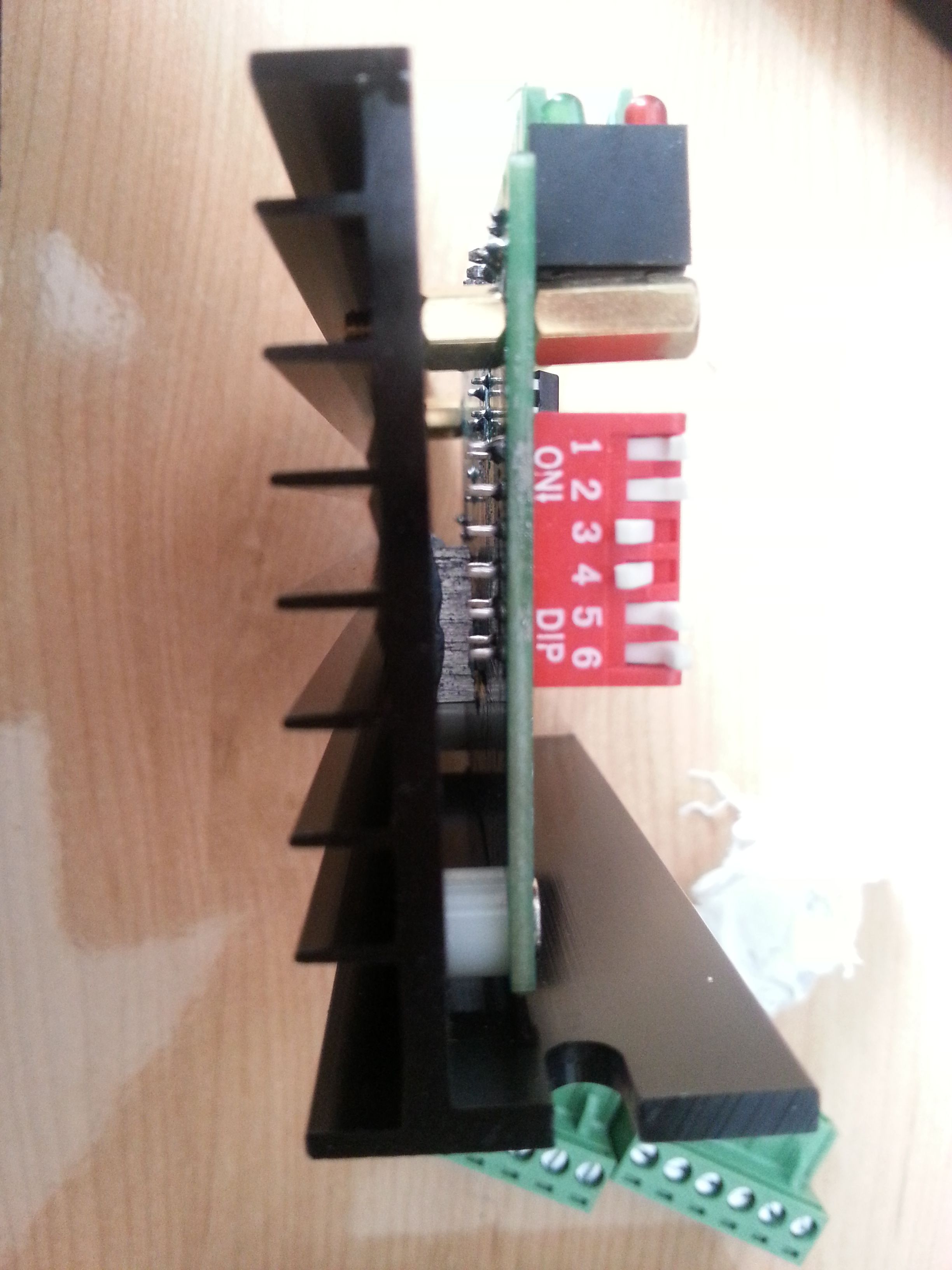
The shims are not at the same height causing a tension on the PCB, the IC and reducing the quality of the contact, even if there is enough thermal paste. It needs just a few shims or 3D print a few to align the PCB.
I will not run those steppers under 48V, components rating is only about 50V it is way too limit also in the datasheet of the Stepper the max supply range is set to 47V (especially for Back-EMF).
I will be interested to check the chopping frequency used on it, I do not like too much noise. They recommend in between 50 to 100 Khz, it depends also on the microstepping setting used. Of course when the chopping frequency is higher, there is more heat generated at the IC.
I will quickly test them under 12V/24V in the forthcoming days to ensure they "work" at least before performing the required modifications.
You just received a 30.77% upvote from @honestbot, courtesy of @boucaron!

Downvoting a post can decrease pending rewards and make it less visible. Common reasons:
Submit
Thank you for collaborating with me to promote this post as explained at https://steemit.com/steemit/@jerrybanfield/10-ways-to-fund-a-steem-growth-project.
Downvoting a post can decrease pending rewards and make it less visible. Common reasons:
Submit