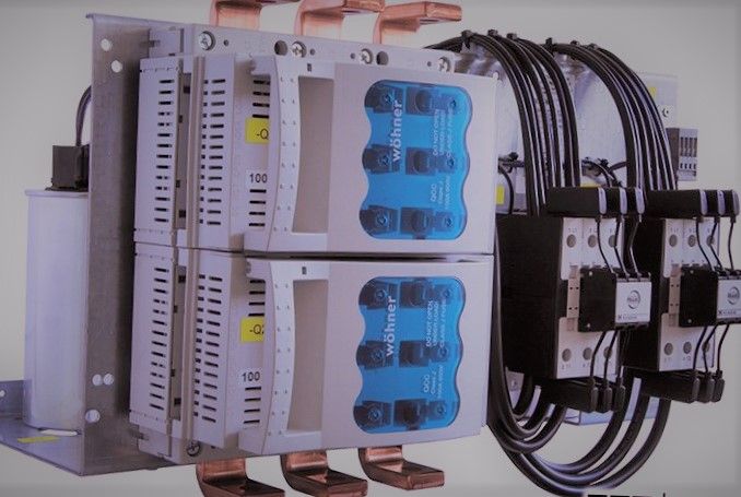
The utility regulations for the allowable size of capacitors permanently connected to a transformer vary according to region. Before installing a PFC system of this type, it is therefore advisable to consult the utility company concerned. If capacitors with fuse switch disconnectors are connected directly to the transformer terminals, the designer should be aware of the fact that the lines to the capacitor are dimensioned for the full short-circuit power.

The modern design of transformer features core laminations that only require a small amount of power for reversal of magnetization. If the capacitor power rating is too high, overvoltage conditions may occur during no-load operation.
If capacitors with fuse switch disconnectors are connected directly to the transformer terminals, the designer should be aware of the fact that the lines to the capacitor are dimensioned for the full short-circuit power.
Typical transformer with permanent power factor correction
Figure 1 – Typical transformer with permanent power factor correction
The capacitor with fuse switch can be directly connected to the terminals of the transformer. This means that the lines to the capacitor must be dimensioned for the full short-circuit power.
Hi! I am a robot. I just upvoted you! I found similar content that readers might be interested in:
http://electrical-engineering-portal.com/download-center/books-and-guides/electrical-engineering/power-factor-correction
Downvoting a post can decrease pending rewards and make it less visible. Common reasons:
Submit