Project Overview
Many people are aware of the infamous railgun, yet very few have ever built one or know how they work. In this blog I will showcase the 4kJ railgun that I constructed for fun. If you are not interested in the physics, skip the Method of Operation section.
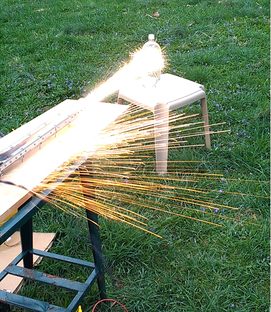
Figure 1. Initial test firing of the railgun at 30 FPS
Method of operation
A railgun works thanks to a few electric and magnetic effects. First off, it is important to understand that whenever an electric current flows through a wire, a magnetic field is created around the wire. This field is circular and forms concentric rings around the wire. The field strength is dependent on the current flowing through the wire as well as how far away you are from the wire. This effect is known as Ampère's circuital law and is the main driving force in most electromagnetic devices. In fact, you can very easily demonstrate this effect by wrapping a coil of wire around a nail and powering it via a small battery(electromagnet)! This effect plays a key role in generating the force needed to propel a projectile.
The second important part to having a functioning railgun is the fact that magnetic field lines cannot cross each other. Although magnetic fields are actually vector fields and are much more complex than simple lines, we can model them as potential lines for our case. Think about what happens when you try and push the "North" sides of two different magnets together. You can feel the repulsion created by the magnetic field lines being pushed closer and closer together. Since they can not cross each other, they are pushed into a smaller and smaller area, effectively creating what is akin to a compressed spring. When you let go of the magnets, they then quickly push themselves apart. It is this force that propels the projectile in a railgun.
So now you may be wondering how do these two things factor into each other? Are there magnets in railguns? Well to answer these questions, we will take a look at how simple railguns are designed. For the most basic railgun, all that is required for operation is conducting rails, a conducting projectile, and a hell of a lot of power. The two conducting rails, which can be seen in Figure 2 below, are separated and are placed parallel to each other.
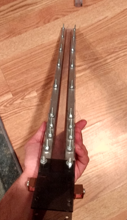
Figure 2. Copper rails with an Aluminum housing and polycarbonate structure.
Placing the rails parallel to each other will allow current to flow up one side and then back down the other when a projectile passes through the center. The projectile in the center is truly key to how the gun operates. Without the projectile passing through the center, there is no current flow and therefore, no magnetic field. However, when a projectile is injected between the rails, it acts as an electrical short, allowing vast amounts of current to flow through it. This large current flows up the rail and generates a strong magnetic field around the rails. This field is fairly uniform all the way up until the current hits the projectile then bam! The electric current makes a sudden right turn and flows through the projectile. All of the sudden you have a 90 degree change in the magnetic field, such that it is actually pushing against the field created by the wire. It is this pushing force created by the magnetic fields that force the projectile down the barrel until it leaves the conductive rails. This is the basic method of how a general railgun works.
My design
My prototype follows the basic form of a railgun fairly well. I did add a layer of mild steel within the Aluminum housing to augment the magnetic field between the rails. I am not sure how well this actually worked, and I will need to perform more analysis to determine the effects.
The power supply for this beast is a 450 V 4kJ capacitor bank that I purchased the components for on Ebay. This is a very large amount of electrical energy, at very dangerous voltages. To put it in perspective, a 30-06 Rifle round has a muzzle energy of 4.035kJ. The electrical discharge energy is on par with a high caliber rile! Unfortunately, this does not mean our projectile energy will be this large. In fact, it is much much smaller due to the inefficiencies of the railgun. The straight electrical discharge is quite impressive however. Figure 3 shows the capacitor banks as well as some of the arc damage from when I discharge the capacitors for storage.
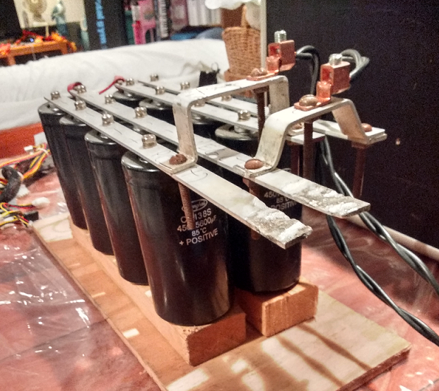
Figure 3. 450 Volt 44800 microFarad capacitor bank (440V operating).
The reason why I use capacitors is that they dump their stored electrical energy very fast. This allows for very high discharge currents and strong fields, which yields faster muzzle velocities. These capacitors are hooked up to either side of the railgun, and when the projectile enters the rails, it completes the circuit and gets pushed forward.
The projectile is injected at an initial velocity via a compressed air channel. The reason for doing this is that if you just place a static projectile between the rails, it will basically just short and explode with little forward motion. This damages the rails and isn't very interesting. By giving it a small initial velocity, the projectile has no chance of getting welded to the rails which would cause it to come to a grinding halt. I used a pilot actuated solenoid to dump a 500mL reservoir of 90psi air to give the projectile its initial kick. This solenoid was essentially the trigger for the system and is what I used to control the firing.
This covers the majority of my railgun project. This was only from my first round of testing and I have made revisions since then. When I get the time to do another test firing, I will document it and then write another article about the results.
Test Firings
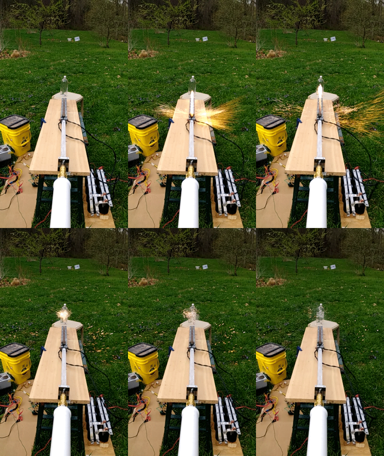
Figure 4. Railgun in slow motion. Framerate was 120fps. The actual .gif was slowed down a bit to better visualize the firing.
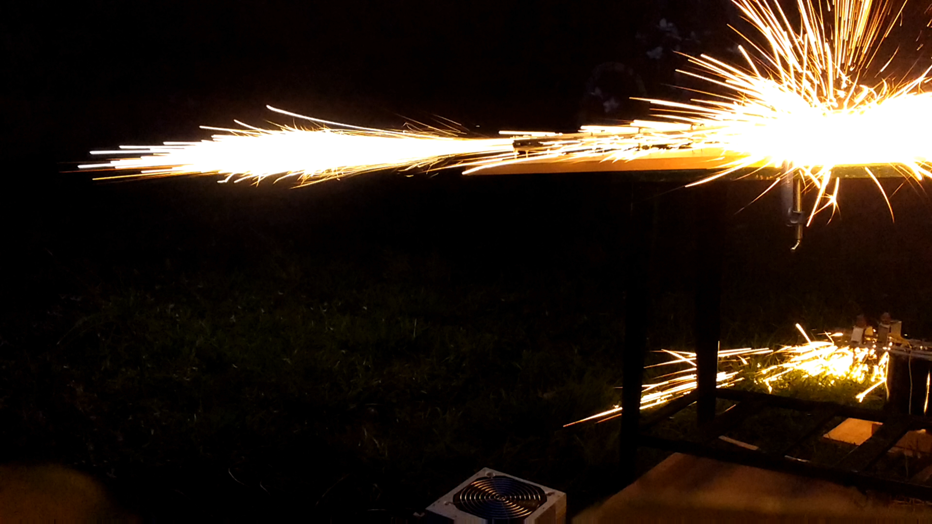
Figure 5. Railgun being fired in low light conditions. Was recorded at 60 fps.

Figure 6. Projectile entered one side of a full 2 liter bottle and was captured within.
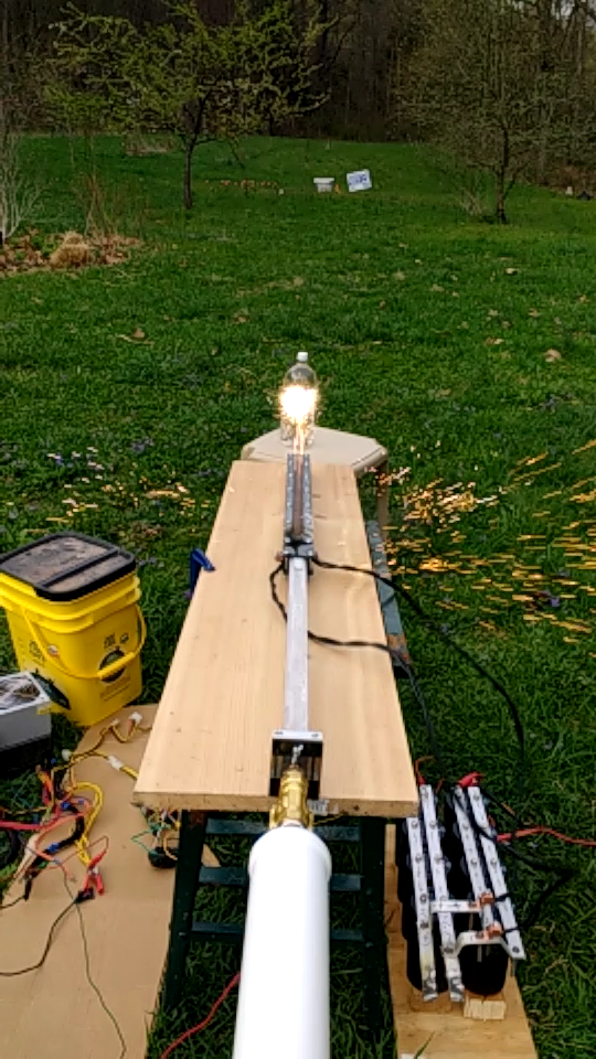
Figure 7. Capture of the slow motion impact. Plasma and molten metal ball is obscuring the actual impact.
I hope you guys enjoyed this read and are now informed about what a railgun is and how it works! If you have any questions or ways I can improve my articles, drop me a comment below!
SOURCES:
Bullet kinetic energies: https://qph.ec.quoracdn.net/main-qimg-adbdc1ef2c4f25b953d75f88db58a574-c
Very nice ! Have you searched into super capacitors ?
Downvoting a post can decrease pending rewards and make it less visible. Common reasons:
Submit
Yes I have and I will give you the reason why I decided against using them!
Super capacitors are excellent for storing large amounts of energy via a very large capacitance value. While this is great for many applications, it is actually not the best for use in fast discharge systems like railguns. Although I said in one of my comments below that I was going to add a series inductor to "slow" the current down a bit, the timescale of this slowdown is still on the order of singular milliseconds. Super capacitors typically cannot discharge the majority of their electrical energy in the time-frame required so for that reason they are not well suited for the task.
Another major factor in not using super capacitors is that they have low operating voltages. The trade-off in having a very high capacitance is that their is much less space between the plates, or graphene sheets in most super capacitors, so there is less of a potential gap meaning a lower breakdown voltage. Having a higher operating voltage for railguns is desired for a few reasons:
1) Ohm's law tells us that Voltage = Current X Resistance. Doing a little bit of rearranging you get Current = Voltage / Resistance. From this we can see that the lower the voltage, the lower the current and therefore, the lower the pushing force on the railgun projectile. Additionally, the power stored in a capacitor is: Power = (1/2) X Capacitance X (Voltage^2). As you can see from this, you get a lot more power from higher voltage than higher capacitance(linear vs quadratic rates).
2) All capacitors are non-ideal in the sense that they have parasitic inductance, especially electrolytic ones. The bigger the capacitor, the large this value typically is. This means that it will take a lot longer for the discharge to reach its peak "steady state" current value. I say "steady state" because on the time scale of the inductor effect, the current is essentially steady. Increasing the voltage increases the current through the inductor.
3) Putting a bunch of smaller capacitors in parallel allows you to have a larger current pulse than what the equivalent singular one would. This is due to the above mentioned parasitic inductance.
There are a few other smaller factors as well, but these 3 are the major ones why I did not use super capacitors. These ones were also a good deal on Ebay:)
Downvoting a post can decrease pending rewards and make it less visible. Common reasons:
Submit
hey are you interested in developing the design and performance?
if so let me know i have a few ideas in mind
Downvoting a post can decrease pending rewards and make it less visible. Common reasons:
Submit
Yes I am! I am always open to new ideas and am looking for external input! One of the updates I made to the design I discussed above was that I added an inductor in series with the capacitor bank and the rails. As you can very clearly see in the .gif above, lots of sparks blast out when the projectile made initial contact. After doing some analysis of the slow motion footage and some other stuff, it looks like a very substantial amount of the energy is being wasted as an explosion at initial contact. I figure that this is caused by the massive current surge vaporizing the initial contacts with the projectile since the projectile is injected at relatively low velocities. The inductor would allow for a gradual increase in current of the projectile which will allow it to utilize more of the rail area for conduction path.
Overall, this upgrade "should" both increase performance and decrease damage to the rails(the current pitting from a single firing is substantial). I put should in quotes because the word itself isn't worth a wooden nickle(fellow engineers you know what I'm talking about).
Let me know what ideas you have!
Downvoting a post can decrease pending rewards and make it less visible. Common reasons:
Submit
Such an amazing technology... and how cool that you built one! Loves watching the footage of the Naval prototypes firing. Perhaps we're ushering in the new age of Battleships. I imagine as power sources and efficiency improve, we'll find them on vehicles and maybe aircraft as well.
Downvoting a post can decrease pending rewards and make it less visible. Common reasons:
Submit
Impressive! So would the only way to eliminate the contact losses from the rail/projectile be to use some form of high speed switching or potentially a different design such as in a coil gun or Gauss rifle?
Downvoting a post can decrease pending rewards and make it less visible. Common reasons:
Submit
Unfortunately, a great deal of the losses stem from resistive and friction forces and not much can be done to mitigate them. There are a few simple things I could do to decrease losses. For starters, Aluminum has a very high coefficient of friction which means it has higher losses than many other metals. The reason I used it for the projectile is it was cheap and easily machinable. In the future I will replace the projectile with a more suitable metal. There are a few other idea's that I am going to test to increase the efficiency of the railgun, but they are worthy of their own articles.
I have built a multistage coilgun before! The problem with coilguns is you need a very large inductor if you want to get the projectile moving a decent speed. This leads to multiple problems since inductors resist changes in current. Basically, it is very difficult to turn them on/off fast enough to achieve decent speeds.
Downvoting a post can decrease pending rewards and make it less visible. Common reasons:
Submit
Makes sense, thanks for the info! I didn't know that about coil guns. (haven't built one myself, yet) Look forward to your future posts!
Downvoting a post can decrease pending rewards and make it less visible. Common reasons:
Submit
I am by no mean an electrical engineer, yet out of curiosity (that's tied to a project I'm working on) let me pose to you this question:
Can a rail-gun model be used to propel a train car along a track? I've seen related designs on yt and I've yet to understand the difference, if there's any, between a rail gun and an "homopolar motor". my angle with this is that the shat of the wheels and the wheels are charged by the current passing through them.
Downvoting a post can decrease pending rewards and make it less visible. Common reasons:
Submit