OK, 44KV is cool and dandy, but for a Tesla coil the 50 Hz is way too low.
To increase this frequency we use a spark gap oscillator.
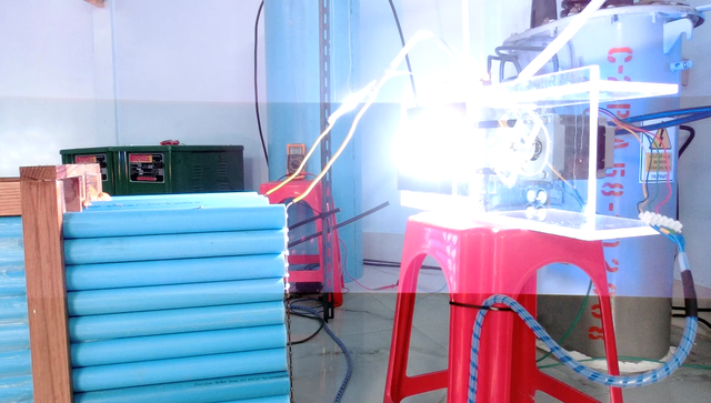
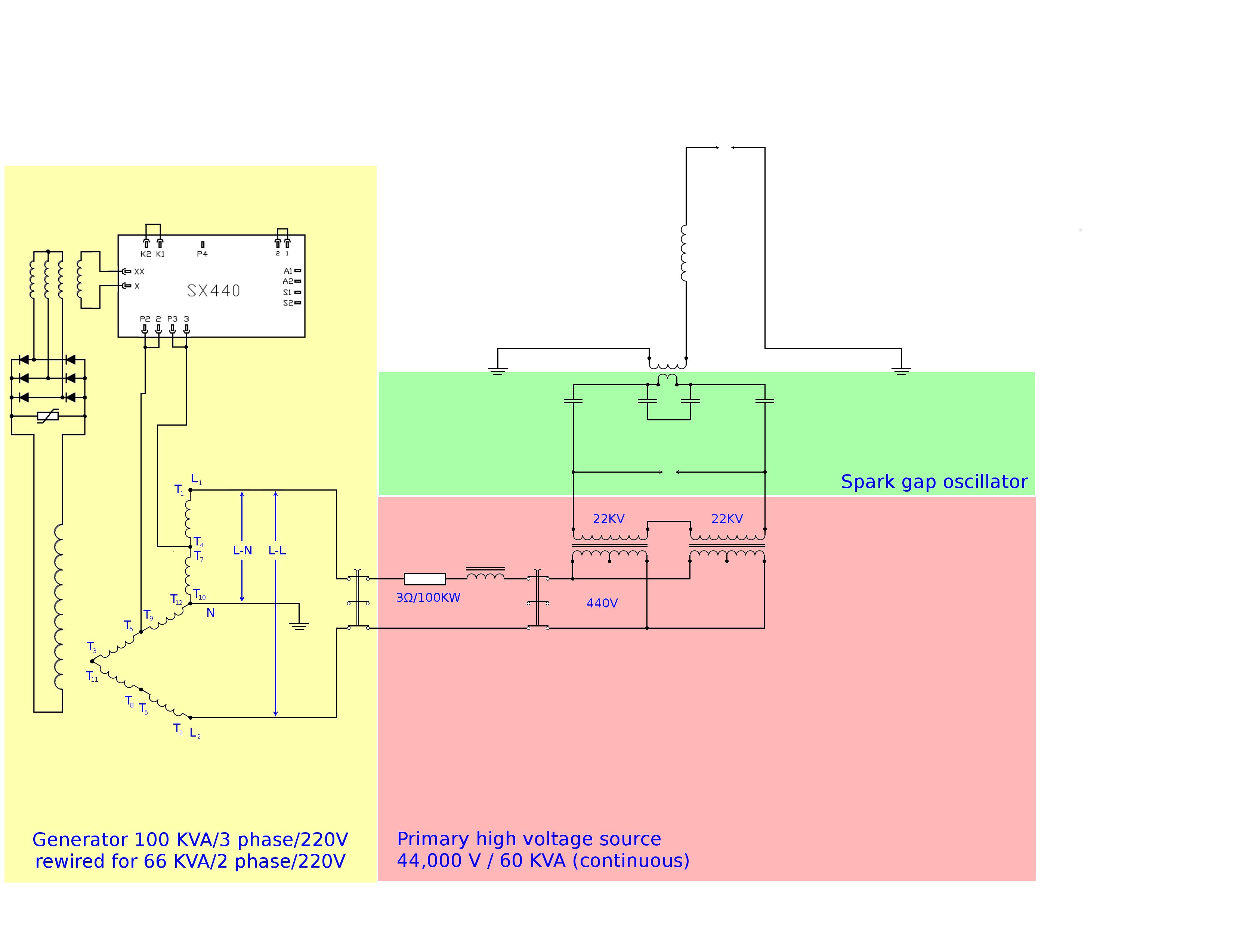
The spark-gap oscillator consists of 3 parts; the primary coil, a capacitor and of course a spark-gap.
Someone once asked me this question: If I have 2 identical capacitors, one charged and one empty, and I connect them in parallel so that the charge gets evenly distributed over both, the voltage will be half of the original voltage, because the voltage is linear dependent on the charge. But that means that the energy in each capacitor is one quarter of the original energy, because this energy is linear dependant on the square of the voltage. So the total energy in the end is half the original energy.
Where did this energy go?
Well, the problem here is that what you think would happen does not actually happen. To connect these capacitors you will need a piece of wire (= inductance and resistance) and when you connect them the charge of the full capacitor will flow to the empty one until they are both half-full. But that is not the end of the story, because of the inductance of the connecting wire the current will continue to flow until ALL of the charge is in the empty capacitor (which is then full, of course).
And from there it will start to flow back, again until all charge has been returned. And this process would continue indefinitely if it wasn’t for the resistance of the wire. This resistance makes that each time some energy gets radiated as electromagnetic waves and some gets converted into heat.
And so that is where the energy goes.
A spark-gap oscillator works on the same principle, but instead of 2 capacitors we have only one of which each time the polarity changes. By shorting a charged capacitor, the charge gets evenly distributed over its plates, but then the inductance of the connecting wire kicks in and transfers the remaining charge as well leaving the capacitor oppositely charged instead of discharged, and so the process repeats.
This way we get a chunk of charge that is moving very rapidly back and forth through an inductor between the two plates of a capacitor.
Normally a spark-gap oscillator consists of these three parts all in series. Then the capacitor is charged by a suitable voltage source until the spark-gap is triggered and it can discharge through the inductor (primary coil).
This is the simplest form of a spark-gap oscillator, but we use a slightly advanced version. We charge another two capacitors and when their voltage is high enough the spark-gap is triggered which causes a voltage reversal across our primary circuit (consisting of our primary capacitor and primary coil). Because this happens extremely sudden, the primary coil blocks this current and we charge our primary capacitor. And consequently an oscillation is started in our primary circuit.
The advantage of this method is that the spark-gap is no longer part of the oscillating (primary) circuit. Thus we have removed a large portion of the resistance from this circuit allowing it to oscillate much longer.
In this post I also briefly talk about this advanced oscillator.
So with this thorough understanding that we now have, let’s turn to the parts.
The Primary Coil
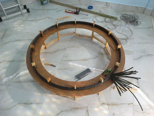
Our primary coil consists of 10 strands, each 25 mm² copper, making just 1 turn.
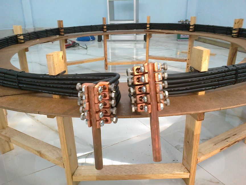
So we have a total of 250 mm² copper in our primary winding. That seems a bit excessive but I want to stay close to anything Tesla wrote, whether or not I fully understand or even agree with it. If we want to prove his theories we must follow his lead.
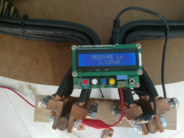
As you can imagine the resistance of this primary coil is very low and its inductance is little over 2 μH as is measured here.
Tesla wrote that in order to have a most efficient transformer, the amount of copper used in the primary should equal the amount used in the secondary.
I can think of one logical reason why that has to be true: In a transformer the product of voltage and current has to be the same in both coils. Now, the voltage is determined by the number of turns and the current by the thickness (actually it is the area) of the wires used. In an average transformer the turns are of equal length, so if the product of turns x wire area is also the same, then there is a same amount of copper in the primary and secondary coils.
Although this makes perfect sense, I have a feeling that this is not what Tesla meant when he said this. Anyway, to avoid endless discussions, as I said we should just do as he said.
The Capacitor Bank
Our capacitor bank is made up of strings of 17 polypropylene capacitors, each good for 3,000V.
In the primary capacitor we use 2 of such strings in series and 10 in parallel. Giving a capacitor of 44.1 nF and 102,000 V.
As extra capacitors we use 20 of these strings in parallel, resulting in 2 capacitors of 176.4 nF and 51,000 V. These two are used in series, so they are actually 88.2 nF and 102 KV.
In total our bank consists of 1,020 polypropylene capacitors.
I have chosen the Cornell Dubilier 940 series because in that series there is a 3 KV version. With 1,440 V/μs this capacitor is a bit slow compared to the Tesla Coiler’s favorite 942 series which does 2,879 V/μs. Though this looks a bit poor at first, since we have 34 in series and each of them does 1,440 V/μs, their combined speed is 48,960 V/μs which is good enough.
The Spark-Gap
For a 44KV spark-gap we go for a multiple-gap-in-series approach, and with a stepper motor and arduino controller I made it in such way that the gap can be adjusted to any required size.
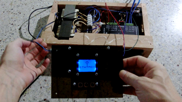
In the back of this picture you see a quite important detail of this spark-gap; a fan.
The powerful discharges in this gap produce a hot plasma between the electrodes. Without the fan this plasma would cause a permanent short of our high voltage source and consequently a poor performance of the coil.
With the fan the gap is extinguished as soon as there is not enough current flowing through it.
Hello, my friend...
I have no idea how I missed this installment!
Please Reply and I will vote for your comment, as I very much want to continue to be a supporter of your good work. ;)
😄😇😄

Downvoting a post can decrease pending rewards and make it less visible. Common reasons:
Submit
Thank you, my surfing friend!
Downvoting a post can decrease pending rewards and make it less visible. Common reasons:
Submit
Looking good so far.
It will be interesting to see how you form up the secondary. How are you going to space the wires, etc.
One thing that is interesting about Tesla, is that he peculiarly good hearing. One of my theories is that he was so good at this because he tuned by ear. Whereas most people who make a Tesla coil tune it by.. it makes a spark, that's good enough.
Downvoting a post can decrease pending rewards and make it less visible. Common reasons:
Submit
Glad you asked about the spacing. I'll get an extra picture of that.
About Tesla's tuning, here is a quote from his pre-hearing interview 1916:
Downvoting a post can decrease pending rewards and make it less visible. Common reasons:
Submit
Fantastic continued documentation once again!
I noticed in your previous videos that you switched over to the simple multiple gap design (as mentioned in Teslas lecture "
Experiments with Alternate Currents of High Potential and High Frequency").
I was curious what your thoughts were on the gains & drawbacks of this design are when compared to the controllable timing of the rotary spark gap.
Downvoting a post can decrease pending rewards and make it less visible. Common reasons:
Submit
Interesting question! I have used a stepper motor controlled rotary spark gap before so to have very precise control over the timing. That of course also requires some other modifications in the HV source, but this precise control was at that point my main focus. The result was that I could generate short pulses at a rate up to about 30 Hz, using up to 3000 Watt.
Now, I would like to operate in a more continuous mode and with more power. 30 BPS is way too low to accomplish this. Also the voltage in the primary circuit is up to 44KV (from 11-22KV earlier) Now it is difficult (but possible) to design a high speed spark gap for 44KV, yet to do it right you will need to adjust the timing of the spark gap to the frequency of your source (50 Hz) and that makes it very complicated.
-- here is an excellent source for more info on that subject --
A static spark gap is by far the easiest solution in this case. And the multiple gap design makes the extinguishing easier.
Downvoting a post can decrease pending rewards and make it less visible. Common reasons:
Submit
Ahh, yes, I remember the thoroughness of that Richie Burnett guy. Good refresher on this subject. Im happy to hear that the multiple sparkgap is the more appropriate choice for CW operation. Its just so darn simple looking. Is there a reason why you wouldn't submerge that in oil as opposed to blowing air across it? I like the idea of a faster, cooler & quieter quench.
I picked up a copy of Tesla's Lecture before the New York Academy of Sciences (April 6, 1897) and was being inspired about his progress with the table top high frequency oscillators and got stuck at his description to what I think he is calling the ballast inductor. He calls it the 'charging coil' to "help raise the pressure to any value desired for charging the condenser."
This lecture was before his learnings at Colorado Springs with his fires, so perhaps its a premature description.
I love the simplicity of his table top oscillators and was hoping to take the learnings in his writings and your learnings here to produce an desktop of my own for experimenting and practicing with tuning. But with some of the new considerations from Mr. Burnett, i'm scratching my head a bit on how to precisely (and simply) think about the ballast / charging coil.
Looks like Tesla doesn't use a step up transformer in his boxes here. :o
Downvoting a post can decrease pending rewards and make it less visible. Common reasons:
Submit
I very much like the oil submerged spark gaps too, but the problem is that the oil needs to be in constant motion otherwise the sparks will burn the oil and cause carbon channels to form. This means that you'll have to build a relatively complicated contraption such as you'll find in Tesla's many patents.
The charging coil is a very simple way to get excessively high voltages. When done correctly, it creates a resonant charging circuit with the capacitor, that resonates at the same frequency as your AC source. I didn't (consciously) use it, but in earlier circuits I used a ballast to limit the current. Inadvertently the ballast I used formed a resonant circuit with my primary capacitors at near 50 Hz. I was expecting 11KV but I killed my ceramic capacitors rated for 40 KV. That was an expensive lesson that I still regret as those ceramic caps were really fantastic in their performance.
If you'd like more details let me know and I'll do a separate post on that.
Downvoting a post can decrease pending rewards and make it less visible. Common reasons:
Submit
oooh, good point, I never really came across anyones documentation on the carbonizing of oil. Im curious what would be the minimum requirement for this to not be a problem. I had some thoughts earlier on mixing Tesla's flat disc viscosity turbine with the rotary spark gap to create some motion in the oil, but then I lost some heart with the complexities of controlling a motor and all its moving parts alongside the complexities of timing and whatnot. Really can't beat the simplicity of a multi spark-gap!
Upon your note of the resonant charging circuit and seeing how simplistic Tesla's circuit evolution descriptions were, I am very interested in hearing more about your expensive lessons on resonant charging! I would love to do away with heavy iron in these desktop designs. Another trademark testament to the importance of understanding "tuning"!
I caused some good curiosity with my Grandpa this Thanksgiving when showing him my illustration work on Teslas 1981 lecture (that you and I have talked about earlier this year), and he asked me if I could build him a high frequency oscillator for his office. I would love to send him something that doesn't require 20lbs of iron and oil for powerful and beautiful operation :D as for my office as well. Yes!
Downvoting a post can decrease pending rewards and make it less visible. Common reasons:
Submit
I'll do a post on resonant charging then, later.
Perhaps for your Grandpa's oscillator it could save a lot of iron if you start out with a high frequency transformer such as is often used with halogen lighting. What they do is, the first create an AC of about 40 KHz and then they use a small step-down transformer to get 12V. This 40 KHz AC will make resonant charging a lot easier (read: less iron required, compact design)
Downvoting a post can decrease pending rewards and make it less visible. Common reasons:
Submit
oh my gosh:
http://www.loneoceans.com/labs/flyback/
How surpassingly simple! :s I love the doing away with the 12v monster DC supply. Now this is what I am talking about!
Makes resonant charging easier? Im ready for the next installment! :)
Downvoting a post can decrease pending rewards and make it less visible. Common reasons:
Submit
You found LoneOceans! Look at his QCW... I tried to contact him, but he does not respond :(
But... erhm... yeah, a flyback circuit is very easy, as is a Slayer Exciter Coil (SEC). Look it up if you are looking for a simple HV source.
Downvoting a post can decrease pending rewards and make it less visible. Common reasons:
Submit
done upvote and comments please back same to you
Downvoting a post can decrease pending rewards and make it less visible. Common reasons:
Submit
Congratulations @mage00000! You have completed some achievement on Steemit and have been rewarded with new badge(s) :
Click on any badge to view your own Board of Honor on SteemitBoard.
For more information about SteemitBoard, click here
If you no longer want to receive notifications, reply to this comment with the word
STOPDownvoting a post can decrease pending rewards and make it less visible. Common reasons:
Submit