Steemian Friends,
Today, I will create lessons for week 01 of Steemit Learning Challenge 22. Today, I will teach my students about Electrical Transformers and the Power Factor. Advanced electrical subjects are to learn about transformers and the power factor. We see the use of electrical transformers and the power factor in homes, offices, and the industrial sector, so today, we will learn about their workings. So, let's start the lesson.
Design By Canva
A transformer is an electromagnetic device that transfers electricity from one place to another without changing its power and frequency. Transformers are of different types based on their construction and application. A transformer has two coils inside it. One coil is the primary, and the other is the secondary. The coils are wound on the winding. The secondary coil is not connected to the primary coil inside the transformer. Transformer works on electromagnetic principle.
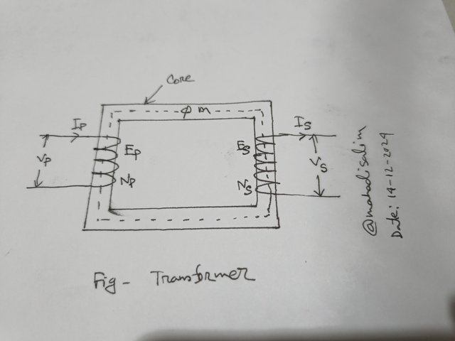
The figure shows the structure of a transformer. The transformer in the figure has two windings: one is primary winding, and the other is secondary winding. The winding is patched between the two cores. There is no electrical connection between the two windings. But there is a magnetic connection. The cores are made of steel, so a magnetic induction is created when power is supplied between them. A transformer transfers electricity from one end to the other through magnetic induction. I hope you understand how the transformer works.
In the figure,
Vp = Primary Voltage
Vs = Secondary Voltage
Ip = Primary Current
Is = Secondary Current
Np = Number of Primary Turns
Ns = Number of Secondary Turns
Ep = Primary Impedance Voltage
Es = Secondary Impedance Voltage.
The above points are very important for transformers. Everyone will learn with importance.
Voltage is supplied to the primary winding of the transformer and connected to the load in the secondary winding. I repeat that there is no electrical connection between primary and secondary winding. A transformer supplies electricity from one end to the other on the principle of flux created by electric induction, i.e. Farad's law. As there is no rotating system inside the transformer like other electrical devices, the transformer's loss is much less.
Relationship between voltage, current, and turn ratio of a transformer:
The turn ratio of a transformer can be found in three ways.
Voltage Ratio:
The ratio of primary voltage (Vp) to secondary voltage (Vs) of a transformer is called voltage ratio.
That is the turns ratio, a = Ep/Es.
Here,
a = turns ratio,
Ep = primary voltage
Es = secondary voltage
Current Ratio:
The current ratio is the inverse of the voltage ratio. The ratio of primary current to secondary current is called the current ratio.
ie current ratio, a = Is/Ip,
where,
a = current ratio,
Is= secondary current,
Ip = primary current
Turns Ratio:
The ratio of primary turns to secondary turns of a transformer is called the turns ratio.
ie turns ratio, a = Np/Ns,
where,
a = turns ratio,
Np = number of primary turns,
Ns = number of secondary turns
Problem:01
If the primary voltage of a transformer is Np, 220 volts, and the secondary voltage is Ns, 440 volts, then what is the voltage ratio of the transformer?
Solution:
We know,
Voltage Ratio,
a = Ep/Es
=220/440
= 0.5 Ans:
Here,
Primary Voltage, Ep = 220 v
Secondary Voltage, Es = 440 v
Voltage Ratio, a = ?
.png)
Design By Canva
HT Bushing:
The primary side of the transformer is the HT bushing. The input voltage is given at the HT bushing. For example, the HT bushing of a 33kV/11kV transformer will be given a 33kV input voltage. The figure above shows the HT bushing of a transformer.
LT bushing:
LT bushing is the secondary side of the transformer. On the LT side, the transformer is connected to the load. LT bushing side of a 33 kV/0.415 kV transformer is 0.415 kV. The figure above shows the LT bushing of a transformer.
Conservator Tank:
Above the transformer, there is a tank like a drum to store oil. This oil storage tank is called a conservator tank. The function of the conservator tank is to keep the transformer's oil as a reserve. When the transformer is running under load, the oil comes out of the body and accumulates there. The Conservator Tank Transformer is shown in the above image.
Buchholz relay:
The Buchholz relay is a safety device in transformers. It stops the transformer in case of transformer oil, coil, or internal fault and prevents accidents. The above figure shows a transformer's Buchholz relay.
Radiator:
The radiator is around the transformer and cools it. When the transformer is under load, the oil is heated, and the oil enters the radiator and cools down a bit. The figure above shows the transformer's radiator.
Temperature gauge:
The meter shows if the oil and coil are hot after running on the transformer load. A thermostat is fitted inside the transformer's body, which displays through a meter and switches off the transformer through a tripping relay in case of overtemperature. The above figure shows the transformer's temperature gauge.
Breather:
The transformer takes air from outside to inside through the breather. The breather contains silica that dehumidifies the air. It is called the transformer's breath. The picture shows the breather.
Transformer oil:
The commercial name of the transformer oil is Pyranol. The amount of oil is determined based on the transformer's configuration. Oil is used to keep the transformer cool and to maintain good insulation of the coils inside. The transformer oil should be checked at regular intervals. This check is called the insulation test. It is very important to check the transformer oil.
Transformers are mainly of four types.
Namely:
- Power Transformer
- Distribution Transformer
- Instrument Transformer
- Auto Transformer
Power transformer:
Power transformers are used in high-voltage lines, such as power supply companies' transmission lines. They have a large rating, i.e., MVA size. We see such transformers in powerhouses.
Distribution transformer:
The transformer used by the electricity companies to reach the customer's house is called a distribution transformer. The transformers on the electric poles in front of our house are distribution transformers, and they are smaller in size.
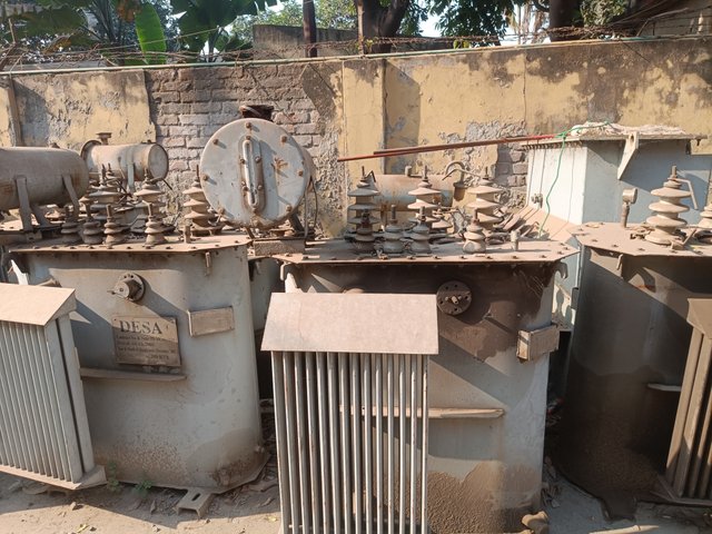
Distribution Transformer
Instrument Transformers:
Instrument transformers convert high voltage to low voltage or low current to measure electricity. For example, in our industrial sector, CT (Current Transformer) and PT (Potential Transformer) are in the 5-ampere range. Instrument transformers measure current.
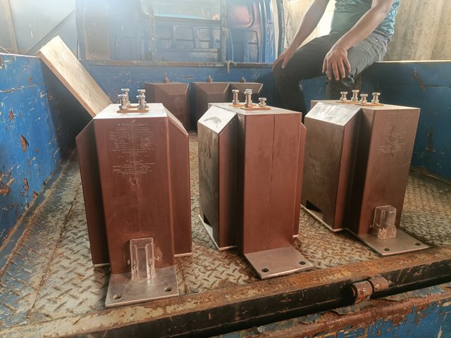
CT & PT
Autotransformer:
Voltage fluctuates when we use electricity at home or in the office. Autotransformers are mainly used to solve voltage-up and voltage-down problems. They are used in UPSs for computers or refrigerators.
Transformers are of two types based on voltage.
Namely:
- Step up transformer
- Step down transformer.
Step-Up Transformer:
Power generation companies use only step-up transformers. After generating electricity, a step-up transformer takes it through a transmission line to a powerhouse. Step-up transformers are larger in rating and size. The step-up transformer converts low voltage to high voltage.
Step-Down Transformer:
Power companies use step-down transformers to deliver electricity to customers' homes. If the electricity in our house is 220 volts, it is done through a step-down transformer. For example, a 440/220-volt transformer is a step-down transformer. Step-down transformers are most commonly used worldwide. The step-down transformer converts high voltage to low voltage.
Transformers are of two types based on the load.
For example:
- Single-phase transformer
- Three-phase transformer
There are generally two types of losses in transformers.
- Core Loss
- Copper Loss
Core loss:
We know a steel core is inside the transformer. The loss in the core when voltage is supplied is called core loss.
Copper loss:
Copper loss occurs between the primary and secondary coil windings in the core inside the transformer.
Also, the transformer has some other losses, such as stray loss, dielectric loss, eddy current loss, and hysteresis loss. We will learn these names in preparation for various electrical tests.
A transformer is tested in various ways. I have named some important tests below.
- Open circuit test
- Short circuit test
The dielectric test of transformer oil is also very important. The quality of transformer oil is checked through this test. Many times, we see the fault of the transformer when the quality of oil decreases in the industrial sector.
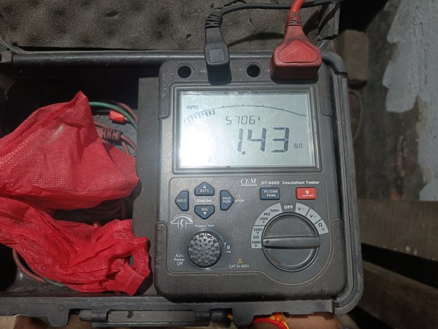 | 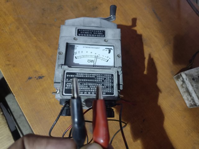 |
|---|
Digital & Analog Meggar
We use megger meters and various types of watt meters to test transformers. However, a Megger meter is the most useful for finding transformer faults. I have given a picture of a mega meter below. Insulation tests are done with a megger meter. The megger meter in the picture below is 5kv ratings and digital. Analogue megger meters are also available.
While doing an industrial job as an electrical engineer or electrician, some important knowledge about transformers is required. I have discussed some of them below. In particular, the transformer rating has to be calculated by calculating the load. For example, a generating unit has a load of 2000 kW.
Problem:02
Now, I have to purchase a transformer for the 2000 KW load. But transformers are rated in KVA. Now, I need to convert 2000 KW to KVA first. I have shown the rules for converting kilowatts to KVA below.
We know,
KVA = KW/PF
KVA = 2000/0.9
= 2222.22~2222 KVA
Here,
KW= 2000
Power Factor(PF)= 0.9
KVA =?
As mentioned above, I need to purchase a 2500 KVA transformer for a 2000 KW load, which is a very important calculation.
The figure shows the nameplate of a power transformer. When I work in the electrical department in the industrial sector, I need to know the details of the transformer by looking at its nameplate. This is a very important point for transformers. Hopefully, all the students will learn the details by looking at the transformer's nameplate.
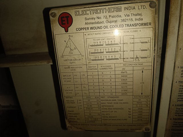
Here,
Step-Down Transformer:
Transformer Rating = 2000 KVA
Primary Voltage(HV) = 33 KV
Secondary Voltage (LV) = 415 V
Current(HV) = 34.99 A
Current(LV) = 2782.41 A
Problem:03
What is the HT and LT current of a 33/11 kV, 5 MVA transformer?
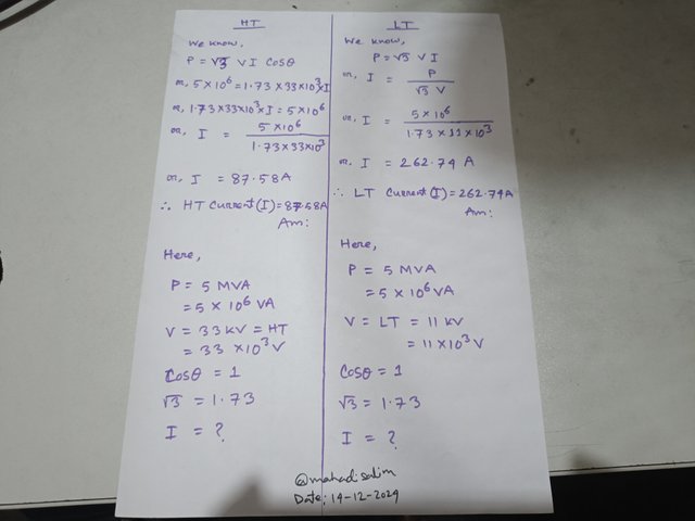
Power factor:
The power factor is the cosine of voltage and current. Otherwise, the ratio of active power to apparent power is called the power factor. The power factor is very important in industrial electrical engineering. The ideal value of the power factor is 1. The power factor has no units. However, the power supply companies in different countries set a perfect power factor value between 1. DPDC, our country's power supply company, fixed the power factor value from 0.95 to 1.00.
Power Factor = KW/KVA
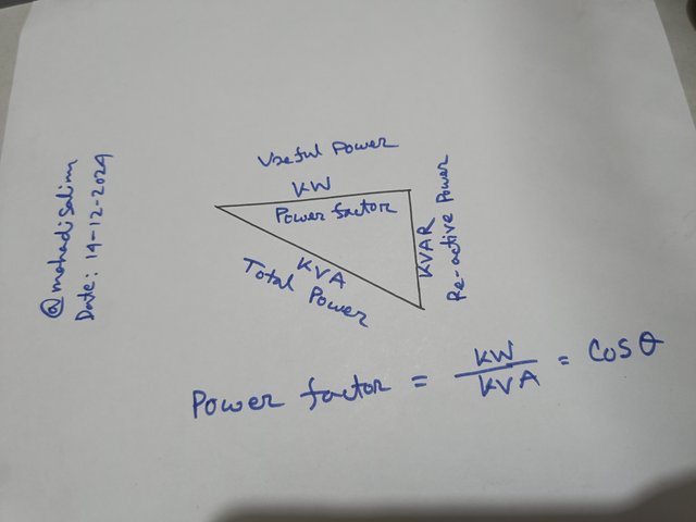
The power factor means how much electricity we use. If the power factor value is not given, we will assume a default value of 0.8. Hopefully, our students have a basic idea of the power factor.
Power Factor Improvement (PFI):
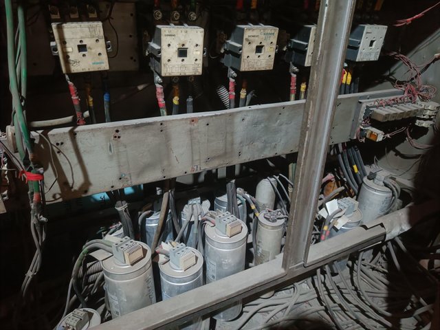
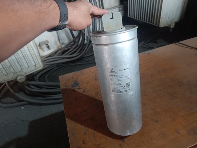
PFI is an important issue for manufacturing companies. An additional electricity charge for PFI is added to the electricity bill if it is less or more than the value prescribed by the electricity companies. So, capacitor banks are used to avoid PFI charges. PFI is arranged in different ways in different countries. However, capacitor banks are used in most of the power sectors.
 |  |
|---|
Power Capacitor & Capacitor Bank
The disadvantages of power factor value are low:
- Power loss.
- The size of the cable has to be increased.
- Efficiency of power devices decreases.
- Product production cost increases due to high electricity consumption.
A.
Name the two transformers from the diagram and explain why.
What is the turn ratio of the two transformers?
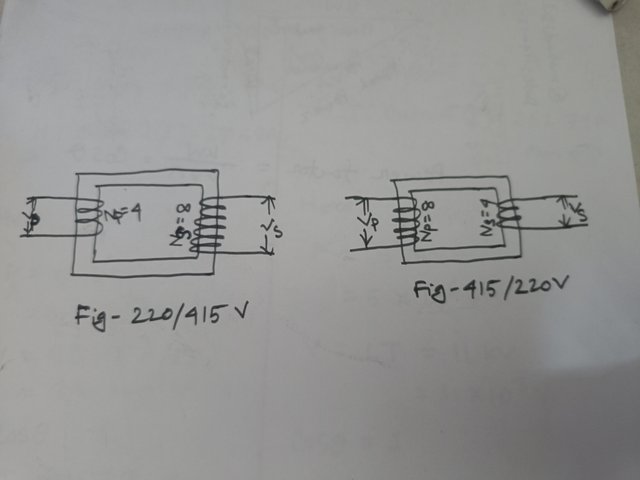
B. Identify the various parts of a power transformer with a picture and write the function of each part.
C. What type of transformer is used for your home's electricity? Describe your understanding with pictures.
D. Calculate how many KVA transformers will be required for a 5000 KW load.
E. Look at the transformer's nameplate in the picture and find out the following points.
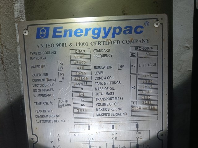
Transformer Name:
Transformer Rating =
Primary Voltage(HV) =
Secondary Voltage (LV) =
Current(HV) =
Current(LV) =
F. Find the currents in the high voltage (HV) and low voltage (LV) sides of the 33/0.415 kV, 2.5 MVA transformer.
G. What do you mean by power factor? What is the power factor value given by the electricity supply company in your country?
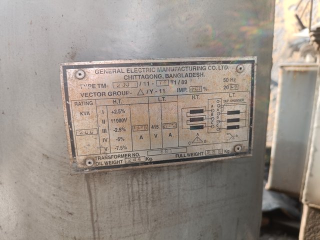
H. Given the nameplates of the two transformers shown in the figure, write three differences.
 |  |
|---|
Determine True/False:
- The name of the oil used in a transformer is pyranol.
- The core loss of the transformer is in the winding.
- The efficiency of the transformer is less than that of other electrical devices.
- The transformer rating is in KW.
- The transformer's insulation test is done with a megger meter.
Marks Distribution:
| Sl. No | Marks | Sl. No | Marks |
|---|---|---|---|
| A | 1.5 Marks | E | 0.5 Marks |
| B | 2 Marks | F | 2.5 Marks |
| C | 0.5 Marks | G | 0.5 Marks |
| D | 1 Marks | H | 1.5 Marks |
- Your title should be "SLC22/WK1: Advanced Electrical Transformers and the Power Factor."
- The content must be #steemexclusive.
- The article must contain the tag #electricity-s22w1.
- Plagiarism is not allowed.
- The link of your task must be added in the comments of this publication.
- Use the burnsteem25 tag only if you have set the 25% payout to @null.
- You can publish homework in any community and in any language. But don't forget to use the original tag.
- Invite three of your active Steemian friends.
- The participation schedule is between Monday, December 16, 2024, at 00:00 UTC to Sunday, - December 22, 2024, at 23:59 UTC.
SC01/SC02 would check on the entire 15 participating Teaching Teams and Challengers and upvote outstanding content. Upvotes are not guaranteed for all articles.
At the end of the week, we would nominate the top 4 users who had performed well in the contest and would be eligible for votes from SC01/SC02.

Best Regards,
Industrial Electrical Instructor
@mahadisalim


This is my Twitter share link :
https://twitter.com/mahadih83660186/status/1868251714165620767?t=6uwXqZw2sv3Xq3w_NaEeeQ&s=19
Downvoting a post can decrease pending rewards and make it less visible. Common reasons:
Submit
I am an electrition and I am very excited for participating in this course so that I can get more knowledge about this field. Dropping my entry soon.
Downvoting a post can decrease pending rewards and make it less visible. Common reasons:
Submit
https://steemit.com/hive-118902/@hisgeneral/slc22-wk1-advanced-electrical-transformers-and-the-power-factor
Downvoting a post can decrease pending rewards and make it less visible. Common reasons:
Submit
My entry :
https://steemit.com/electricity-s22w1/@shadow04/slc22-wk1-advanced-electrical-transformers-and-the-power-factor
Downvoting a post can decrease pending rewards and make it less visible. Common reasons:
Submit
My entry
https://steemit.com/electricity-s22w1/@drcrypto1/slc-s22-w1-advance-electrical-transformers-and-power-factor
Downvoting a post can decrease pending rewards and make it less visible. Common reasons:
Submit
My entry
https://steemit.com/electricity-s22w1/@josepha/slc22-wk1-advanced-electrical-transformers-and-the-power-factor
Downvoting a post can decrease pending rewards and make it less visible. Common reasons:
Submit