We must find a way to keep drinking men in check so they don't become a nuisance to society and a cause of death.Too many persons have lost their lives by carrying out actions under the influence of alcohol and this circuit was built to curb it.
The breathalyzer circuit has being built to check the drunken state of drivers to know the content of alcohol in their system.
it has evolved over the years. from the Alcometer, Intoximeter, drunkometer etc.
This simple breath analyser circuit consists of an an alcohol sensor (MQ2) and LED driver (lm3914) and resistors and light emitting diodes (used for level indication).
THE SENSING AND TRANSDUCING UNIT
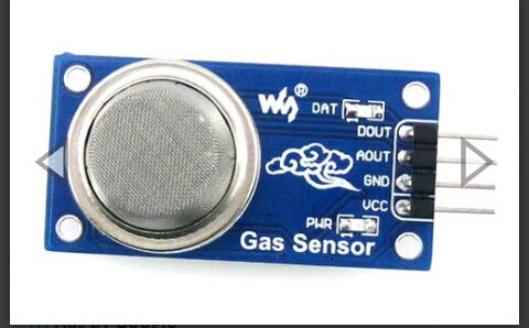
The sensor used in this design is the MQ2 sensor module. MQ-2Alcohol Sensor is an alcohol sensor that detects the concentration of alcohol gas in the air and an analogue voltage is an output reading.
MQ-2 is an alcohol sensor that can be used to measure or detect breath alcohol concentration. It is a highly sensitive (i.e. it can be used to detect alcohol with different concentration) sensor with fast response time. MQ-2 can also detect Benzene, Methane, LPG, Carbon monoxide and Hexane. The alcohol sensor is a 6 pin device out of which 4 pins are used to fetch signals and other 2 are used to provide current to heater coil.
Sensitive material of MQ-2 gas sensor is SnO2, which with lower conductivity in clean air. When the target alcohol gas exists, The sensor’s conductivity is more higher along with the gas concentration rising. A simple electronic circuit can be used to Convert change of conductivity to correspond output signal gas concentration.
MQ-2 gas sensor has high sensitivity to Alcohol, and has good resistance to disturb of gasoline, smoke and vapour. The sensor could be used to detect alcohol with different concentration; it is with low cost and suitable for different application.
CHARACTERISTICS OF THE SENSOR
Good sensitivity to alcohol gas.
Long life and low cost.
A Simple drive circuit.
TECHNICAL DATA
Concentration: 0.05mg/L – 10mg/L
Operating voltage: 5V±0.1
Current consumption: 150mA
Operating temperature: -10 ºC to 70ºC
THE COUPLING UNIT
The potential from the output of the MQ2 sensor is sent through a potential network to give a desires output. on the divider network there are two resistors R1 and R2(closest to ground). the output voltage is Vin X R2/(R1+R2). the Vin is the voltage input from the MQ2 sensor.
from the equation, we would see that the larger the value of R2 and R1 and Vin kept constant the higher the output voltage. thus, R2 is the sensitivity factor.
THE DISPLAY
Our output from the potential divider is sent to the signal input of the lm3914 (pin 5) and integrated circuit. this driver drives 10LEDs at the output. it has two modes. dot and bar which can be controlled by setting the pin 9 of the driver low or high.
the choice is left to the user.
The higher the concentration of the alcohol sensed, the greater the potential at the divider network, the more LEDs turned on.
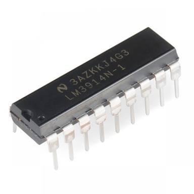
these LEDs are current driven devices therefore, the current output from the LM3914 must be controlled inorder to not burn out the LED.
the average current rating for the LEDs is 15mA. the resistor at input to pin 7(which is already connected to pin 6) is 2.2K (R2) and 1K (R1). they both constitute a divider network with it's potential connected to pin 8 of the LM3914. pins 2,4 and 3 are connected to ground and Vcc respectively.
the circuit has its inbuilt power pack for high current ouptut.
the LM3914 has a current rating of 150mA and so the bridge rectifier and the transformer used in the circuit is both 1A and 300mA respectively.
The power pack was used instead of the battery since it would be producing a constant current and voltage to the breathalyzer circuit.
The LM3914 is a negative logic. that means that its output is a logic OV thus all the anodes of the LEDs are connected to the positive power (Vcc).

The circuit was tested using the basic methylated spirit used in clinics and it gave a reading of 4 LEDs turning on.
The circuit diagram :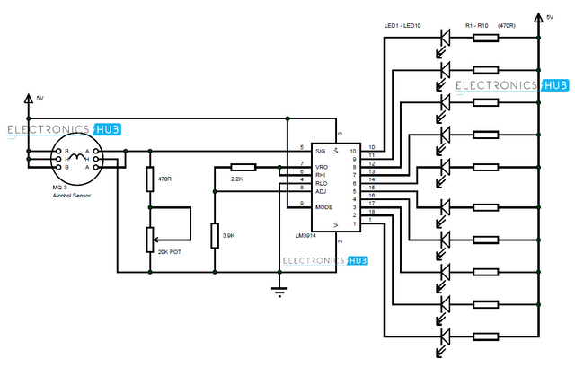
Based on the color configuration used, 4LEDs are green (indicating small traces) 2LEDs are yellow(indicating way past normal) and 4LEDs are red ( which indicates a dangerous level).
The fully soldered circuit is below. It was daunting at first, but it was worth it.
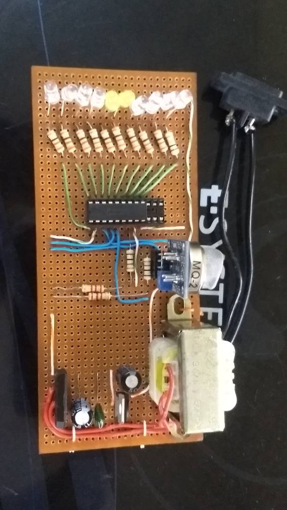
quite a cool circuit. small and efficient.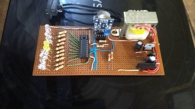
You won an Honorable Mention!
😎
Downvoting a post can decrease pending rewards and make it less visible. Common reasons:
Submit
jesus Christ of Nazareth.....anyways smart one bro
Downvoting a post can decrease pending rewards and make it less visible. Common reasons:
Submit