Have you ever wondered, amused and bewildered on how you have been able to watch and listen to live programs (such as political rallies, religious activities, sporting activities, and many more) that were transmitted within and outside your environment? If yes, follow me as I explain the working principle of transmission and communication.
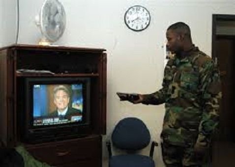
Television is an amazing window on the world. At the flick of a button, you can travel from the North Pole to the Serengeti, watch men walking on the Moon, see athletes breaking records, or listen to world leaders making historic speeches. Television has transformed entertainment and education; in the United States, it's been estimated that children spend more time watching TV (on average 1023 hours a year) than they do sitting in school (900 hours a year). Many people feel this is a bad thing. One of TV's inventors, Philo T Farnsworth (1906–1971), came to the conclusion that television was hopelessly dumbed down and refused to let his children watch it. Whether TV is good or bad, there's no doubting that it's an ingenious invention. But how exactly does it work? Let's take a closer look!.source

Television (TV) is a telecommunication medium used for transmitting moving images in monochrome (black and white), or in color, and in two or three dimensions and sound. The term can refer to a television set, a television program ("TV show"), or the medium of television transmission. Television is a mass medium for entertainment, education, news, politics, gossip and advertising.source
Transmission
This is the distribution of audio and/or video signals (content) to a dispersed audience via any electronics mass communications medium, but typically one using the electromagnetic spectrum (radio waves).
Transmission of radio and television programs from a radio or television station to home receivers is refer to as OTA (over the air) or terrestial broadcasting and in most countries requires a broadcasting license.
Types of transmission
- Satellite transmission
- Terrestrial transmission
- Microwave transmission
- Streaming
Satellite transmission
This type of transmission consists of sending a signal from the earth station to the satellite in the orbit. The process of sending a signal is called Uplinking and the process of retrieving the signal back to the earth by another station is called Downlinking. The frequencies at which the system works are called uplinks and downlinks frequencies. The main advantage of this type of transmission is that it covers a large area. The up linking frequency is higher than the down linking frequency because of interference of the signal.
C-BAND DISH: The most commonly used disc in broadcasting outfit: this is the dish used in transmitting both audio and video signals because of its wavelength which is greater than the KU dish which is always affected by rainfall. The wavelength of rainfall is the same as that of the KU dish, this is the main reason why signal buffs most time. The dish is erected by 8-9m above the ground level for upmost signal.
Microwave transmission link
A microwave link is a system of communication that transmit data, audio, video or both contents over a short or long distance between two locations with the use of microwave frequency.
Microwave links are generally used in broadcasting outfit to transmit programmes to a very wide range or to receive outside signal across countries back to the studio.
The final signal (output) coming from the master control room through the audio and video coaxial cable into the input of the microwave transmitter at links before onward transmission through radio waves.
Properties of microwave links
- Involve line of sight (LOS) communication technology
- It can be greatly influenced by environmental constraints, including rain fade
- Have very limited penetration capabilities through obstacles such as hills, buildings and trees
- Sensitive to high pollen count
- During solar proton events signals can be degraded
Uses of microwave links
- In communications between satellites and base stations
- As backbone carriers for cellular systems
- In short range indoor communications
- Telecommunications, in linking remote and regional telephone exchanges to larger
(main) exchanges without the need for copper/optical fibre lines.
A typical broadcasting outfit or station must have the following compartments:
- Power room
- Studio room
- Control room
- Transmitter room
- Transmitting antenna
Power room
Due to the various system and different electronic circuit involved in the transmitting
section, the transmitting hall uses both direct currents and alternating current at different
required units. The main power source at this stage is the 3-phase 415V A.C supply.
However, there are sub-power units at various stages depending on the equipment.
The studio room
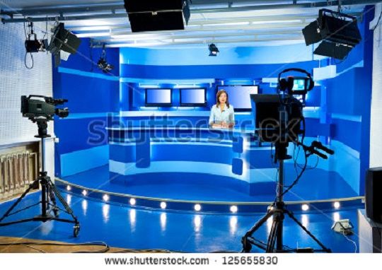
This room is sometimes referred to as the continuity studio. It is the source for information generation. It is a well padded in other to eliminate reverberation and interference of sound waves. This is where live and recorded programs are being carried out for viewers and it may be transmitted simultaneously if so desired e.g. in news casting for easy dissemination of information and communication.
Broadcasting studios or continuity studios are acoustically padded, sound enhanced rooms where the relay of lives, canned and recorded programs are done. The importance of adequate engineering principles in the design cannot be underestimated as this would make or mar the overall production. The studio is padded so that it can eliminate reverberation of sound wave. The studio is illuminated to eliminate background image and shadow.

Operating theory and principle
Studios are used for generating both audio and video signals for production of live programs and initial production of recorded ones. The electronic setups are usually complex as they consist of a gargantuan network of audio and video cables which are then lumped up together and connected to the MCR for onward transmission. The audio pickup of these studios is done by Omni-directional ribbon and cardioid microphones which are powered by audio mixers connected by cannon (XLR) cables with a direct current supply of 48 volts.
The video capture is done by high vision digital cameras on tripod stands. The images are captured through the iris of the cameras which are directly connected through DIN cables to the camera control units (CCU) where colour separation and analyses is performed.
Studios are also properly lighted by halogen lamps with a power rating of between 800W and 1500W which are between six and ten in number depending on studio size. Proper lighting enhances vision clarity and enhances effective colour conation just like the human eye. In the studios we have what is called a
Real set and a Virtual set in which their explanation goes thus;
Real set – It is a kind of setting we have in a studio where things are recorded and viewed just exactly the way they are seen real life i.e. programmes are shown exactly the way they are viewed based on their real background setting.
Virtual set – It is a kind of setting we have in a studio where a kind of plain background setting is used in the studio but its final output is tweaked to the particular graphical background we want or in broadcasting terms what we call Chroma keyed (superimposing) through the use of a computer system.
Some of the components that can be found in the studio are listed below
- Camera
- Stage Lighting
- Microphone
Camera: A camera is an optical instrument that records images that can be stored directly, transmitted to another location, or both. These images may be still photographs or moving images such as videos or movies. A camera may work with the light of the visible spectrum or with other portions of the electromagnetic spectrum.source

A still camera is an optical device which creates a single image of an object scene, and records it on an electronic sensor or photographic film. All cameras use the same basic design: light enters an enclosed box through a converging lens and an image is recorded on a light-sensitive medium
Principle of camera
We have two (2) types of camera namely;
- Charged couple device (CCD)
- Complementary metal oxide semiconductor (CMOS)
Complementary metal oxide semiconductor (CMOS)- CMOS technology is used in microprocessors, microcontrollers, static RAM, and other digital logic circuits. CMOS technology is also used for several analogue circuits such as image sensors (CMOS sensor), data converters, and highly integrated transceivers for many types of communication.
Two important characteristics of CMOS devices are;
- high noise immunity
- and low static power consumption.
Since one transistor of the pair is always off, the series combination draws significant power only momentarily during switching between ON and OFF states. CMOS devices do not produce as much waste heat as other forms of logic, for example transistor-transistor logic (TTL) or CMOS logic.
CMOS also allows a high density of logic functions on a chip. It was primarily for this reason that CMOS became the most used technology to be implemented in VLSI chips. CMOS refers to both a particular style of digital circuitry design and the family of processes used to implement that circuitry on integrated circuits (chips). CMOS circuitry dissipates less power than logic families with resistive loads. CCD and CMOS image sensors are two different technologies for capturing images digitally.
Each has unique strengths and weakness giving advantages in different applications. Both types of imagers convert light into electric charge and process it into electronic signals. In a CCD sensor, every pixel’s charge is transferred through a very limited number of output nodes (often just one) to be converted to voltage, buffered and sent off-chip as an analogue signal. All of the pixel can be devoted to light capture, and output’s uniformity (a key factor in image quality) is high.
In a CMOS sensor, each pixel has its own charge-to-voltage conversion, and the sensor often includes amplifiers, noise-correction, and digitization circuits, so that the chip outputs digital bits. These other functions increase the design complexity and reduce the area available for light capture.
To be continue in the next post
Thanks for reading
note: all pictures used are labelled for reuse