The junction field effect transistor or JFET is one of the least complex transistor from the auxiliary perspective. It is a voltage controlled semiconductor gadget. In this, the current is conveyed by just a single sort of transporters. Along these lines, it is a unipolar gadget. It has a high info electrical resistance.
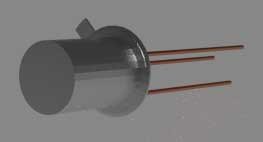
Image credit: JFET
JFET comprises of a doped Si or GaAs bar. There are ohmic contacts, the two closures of the bar and semiconductor intersection on its two sides. On the off chance that the semiconductor bar is n-type, the two sides of the bar is vigorously doped with p-type polluting influences and this is known as n-channel JFET.
JFET comprises of a doped Si or GaAs bar. There are ohmic contacts, the two closures of the bar and semiconductor intersection on its two sides. On the off chance that the semiconductor bar is n-type, the two sides of the bar is vigorously doped with p-type polluting influences and this is known as n-channel JFET.
Then again if the semiconductor bar is p-type, the two sides of the bar is vigorously doped with n-type polluting influences and this is known as p-channel JFET. At the point when a voltage is connected between the two closures, a present which is conveyed by the dominant part bearers of the bar streams along the length of the bar. There are a few terminals in JFET. The terminal through which the lion's share bearer enter the bar and the terminal through which they leave are known as source (s) and deplete (D) individually. The vigorously doped locale on the two sides is known as the entryway (G).
In intersection field impact transistor, the intersection is an invert one-sided. Thus, consumption areas frame, which reach out to the bar. By changing entryway to source voltage, the exhaustion width can be controlled. Along these lines, the viable cross segment territory diminished with expanding reverse inclination. Thus, the deplete currentis a component of the entryway to the source voltage
Presently days JFET is out of date. Its candidates are restricted to circuit plan. Where it can be utilized a speaker and as a switch both.
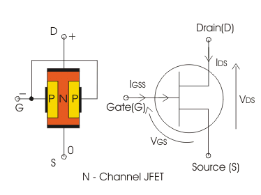
N-Channel JFET
.png)
Image Credit: @helen001
A semiconductorbar of n-type material is taken and ohmic contacts are made on either finishes of the bar. Terminals are brought out from these ohmic contacts and named as deplete and source as appeared in the figure underneath. On the other two sides of the n-type semiconductor bar, vigorously doped p-type locales are framed to make a p-n intersection.
Both these p-type areas are associated together by means of ohmic contacts and the door terminal is brought out as observed underneath. Figure underneath demonstrates the n-channel and p-channel JFET with images. The bolt on the entryway demonstrates the heading of the current. currentcourses through the length of the n-type bar (channel) because of greater part charge conveys which for this situation are electrons. At the point when a voltage is connected between the two finishes, a present which is conveyed by the larger part bearers electrons streams along the length of a bar. The greater part bearers enter the bar through the source terminal and leave through the deplete terminal. The intensely doped districts of the n-type bar are known as the entryways.
The entryway source intersections is turn around is one-sided subsequently consumption districts from which stretch out to the bar by changing door to source voltage compelling cross sectional zone diminishes with the capacity of the door to source voltage.
P-Channel JEFT
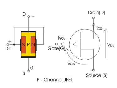
Image credit: @helen001
p-channel JFET comprises of a p-type silicon or GaAs. Two sides of the bar is vigorously doped with n-type debasements. At the point when a voltage is connected between the two closures, a present which is conveyed by the greater part transporter gaps stream along the length of a bar.
The entryway source intersection is turn around one-sided subsequently exhaustion areas shape, which reach out to the bar by changing door to stretch out to source voltagethe consumption width can be controlled. The powerful cross sectional zone diminished with expanding reverse predisposition, so the deplete current is the capacity of the entryway to source voltage.
Biasing of JFET
The door to source p-n intersection of a JFET is constantly invert one-sided and supply voltageis given over the deplete to source terminal.
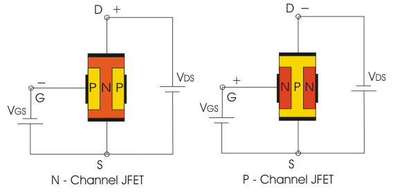
Image Credit: @helen001
Activity of Intersection Field Impact Transistor or JFET
Activity with door to source voltage = 0
In the event that a n-channel JFET is one-sided as clarified above and the door to source voltageis kept zero, because of the positive deplete to source voltagecouple of electrons which are accessible for conduction in the n-type material will begin spilling out of the restricted section (channel) from source to deplete. This current is called as deplete current. As the channel has some limited opposition it will cause some voltagedrop over the channel. Henceforth the exhaustion area of the pn junction begins expanding and infiltrates more into the n-type material as it is softly doped. Because of this the width of the channel accessible for conduction is lessened. The infiltration of the consumption district into the n-type area relies upon the invert predisposition voltage. Most extreme deplete current ID(MAX) will course through the gadget when the channel is amplest i.e. at the point when VGS is zero.
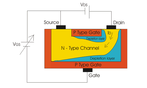
Image Credit: @helen001
Task with negative gate to source voltage
As a negative voltage is connected to the door to source pn junction the exhaustion district increments and entrance of the consumption locale into the n-type channel additionally increments. On the off chance that the negative entryway to source voltageis additionally expanded the exhaustion district spreads increasingly inside the n-type bar. Because of this less and less number of charge conveys (electrons) can go through the channel and the deplete current diminishes. Thus, with increment in negative entryway to source voltagedeplete currentdecreases. At a specific estimation of this voltagethe exhaustion area from both the finishes will increment and contact each other and the deplete currentwill end up zero. This entryway to source voltageat which deplete currentis cutoff is called as VGS(OFF). As observed the VGS controls ID. Henceforth, JFET is a voltage controlled gadget. The connection amongst ID and VGS is given by Shockley's condition

Where, VP is the squeeze off voltagewhich is the estimation of deplete to source VDS at which deplete current achieves its steady immersion esteem. Any further increment in VDS does not influence ID.
JEFT Attributes or Intersection Field Impact Transistor Qualities
In this attributes we can discover three districts,
The Straight or the Ohmic District: Here the deplete to source voltageis little and deplete current in about corresponding to the deplete to source voltage. At the point when a positive deplete to source voltageis connected, this voltageincrements from zero to a little esteem, the consumption locale width stay little and under this condition the semiconductorbar acts simply like a resistor. Thus, deplete current increments straightly with deplete to source voltage.
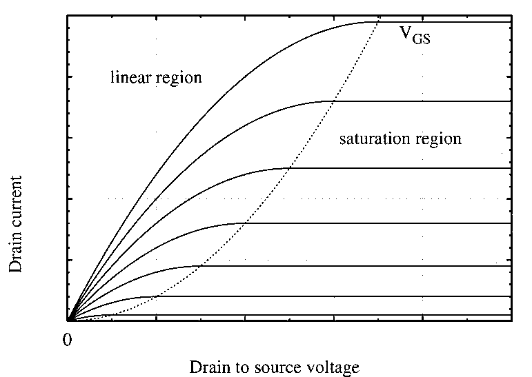
Image Credit: @helen001The Immersion of the Dynamic District: Here the deplete current is relatively steady and it isn't reliant on the deplete to source voltagereally. At the point when the deplete to source voltage constant to expand the channel resistance increments and eventually, the exhaustion locales meet close to the deplete to squeeze off the channel. Past that squeeze off voltage, the deplete, currentachieves immersion.
The Breakdown Voltage: Here the deplete current increments quickly with a little increment of the deplete to source voltage. As a matter of fact for extensive estimation of deplete to source voltage, a breakdown of the entryway intersection happens which comes about a sharp increment of the deplete current.
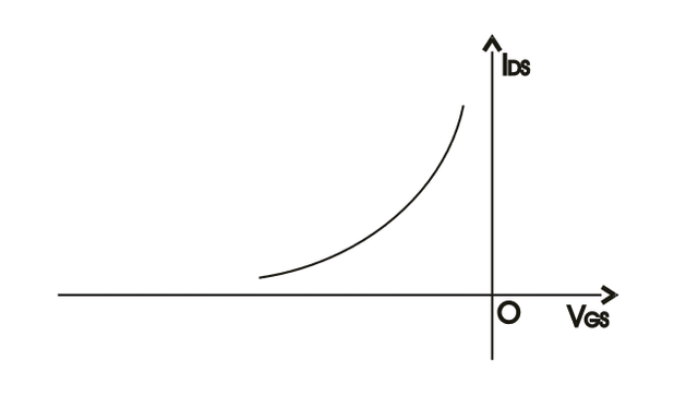
Exchange Qualities
The graphical qualities plot of the immersion deplete currentagainst the door to source voltageis known as the exchange attributes of JFET. It can be gotten from static attributes effectively. The exchange attributes of a n-channel is demonstrated as follows
JFET as Switch
The intersection field impact transistor (JFET) can be utilized as an electronically controlled change to control electric energy to a heap.
JFET's are typically on (NO) gadgets. They are ordinarily soaked gadgets. At the point when a turn around inclination is connected amongst door and source, the exhaustion locales of that intersection extend and squeezing off the channel through which currentstreaming happens. On the off chance that the channel is squeezed the current does not stream the gadget will be in turned off condition. By this procedure intersection field impact transistor can be utilized as switches. Be that as it may, now days their application is outdated. A case of JFETs going about as a switch and the relating circuit is given underneath.
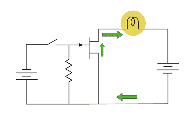
Image Credit: @helen001
Utilizations of JFET
The intersection field impact transistor has numerous application in the field of gadgets and correspondence.
A portion of these applications are expressed beneath.
Low Clamor and High Information Impedance Speaker:-
Commotion is an unfortunate aggravation which meddles with the signs data - more prominent the clamor less the data. Vitality gadgets gadget cause some measure of clamor. On the off chance that FET s is utilized at the front end, we get less measure of opened up commotion at the yield. Presently, it has high info impedance. Along these lines, it can be utilized as a part of high info impedance speaker.Cradle Enhancer:-
Cradle enhancer ought to have high information impedance and low yield impedance. On account of high I/p impedance and low yield impedance, FET goes about as awesome support intensifier. the regular deplete mode can be utilized as a part of this reason.R.F. Amplifier:-
JFET is great in low current flag activity as it is a voltagecontrolled semiconductorgadget. It has low commotion level. Thus, it can be utilized as RF speaker in collector areas of correspondence field.Current Source:-
Here all the supply voltageshows up crosswise over load. In the event that the present attempts to increment in particular, the unnecessary load a present drives the JFET in to dynamic locale. Hence JFET goes about as a current source.Switch:-
JFET might be utilized as an on/off switch controlling electrical energy to stack. A case is given beneath
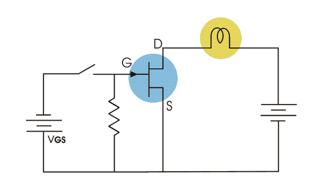
Image Credit: @helen001
Chopper:- When a source wave is connected to the door of JFET witch, the chopper task should be possible utilizing JFET.
Multiplexer:-
Simple multiplexer circuit can be made utilizing JFETs. A case is given underneath.
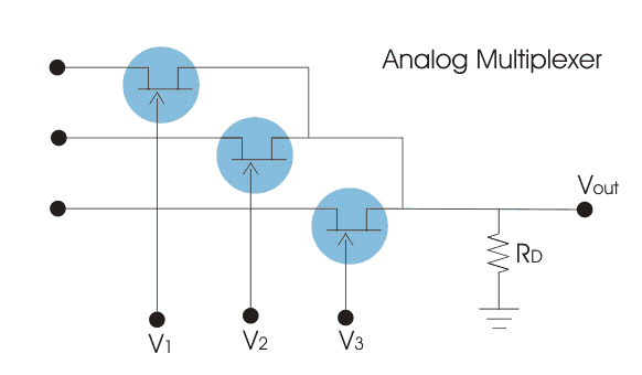
Image Credit: @helen001
Good write up. Thank you for explaining in details what a JFET is and it's working principle. But did you produce the images yourself? Cos I think the credit is not well stated.
However, there some areas you might need help in improving. If you already are part of the steemstem community on discord, Pls request for a mentor. And if not let me know so I can give you the link to join.
Downvoting a post can decrease pending rewards and make it less visible. Common reasons:
Submit
i'm not
Downvoting a post can decrease pending rewards and make it less visible. Common reasons:
Submit
For the steemstem community, join using this link.
If you want to join the Nigerian community on the stemng community, here is the link
Once you join, indicate your desire to get someone to mentor you.
However, I noticed your post keeps duplicating itself. Is that your doing or a bot?
Downvoting a post can decrease pending rewards and make it less visible. Common reasons:
Submit
its my doing... is it bad?
Downvoting a post can decrease pending rewards and make it less visible. Common reasons:
Submit
Yes it is bad. Just download discord and join us and get some help
Downvoting a post can decrease pending rewards and make it less visible. Common reasons:
Submit