About 9 days ago , I have posted the first part of this article .Now I am publishing the 2nd part. Last few days was not really good for me . I broke my right arm again. this time not so serious. Doctor suggest me to hang my arm in bag. Now I am good thanks to the Almighty.
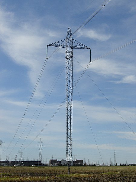
HVDC system stands for High Voltage Direct Current transmission system, which transfer huge amount of power(100KV to 1500KV) without any lose from one place to another. Basically It is used in long distance about 500 km or more . In ac system when we send power there are so many loses occur. In DC system we avoid it. and will get a continuous power flow. Which means we can get an improved transient stability. By using this we can supply great amount of power those areas where we can't build power plant . For more introduction you can see my last post.
Control & Performance analysis of VSC-HVDC Transmission System:: Chapter-1(part-2)
Report of Review:
Literature review from different technology. An efficient source reveals the following things about VSC-HVDC rapid and independent control over both active and reactive power improves the transient stability. VSC- HVDC compared with new AC transmission line improves the stability.
Basically, it greatly enhances the voltage stability and kept it from collapsing due to lack of reactive power together wide area system. Hybrid AC/DC transmission system measurement system could manage the overall power grid operation security and efficiency.
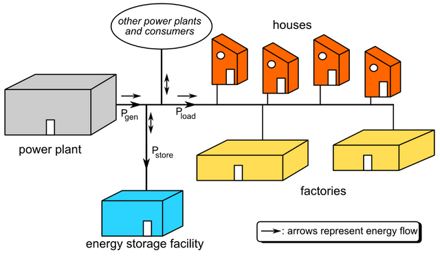
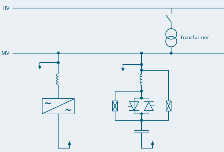
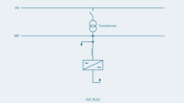
Hybrid AC/DC grid structure enables efficient congestion management, reliable integration of large scale renewable energy sources and improve system dynamic response against disturbances . It can prevent voltage collapse by using gradual P(active) & Q(reactive) modulation including reducing the active power to increase reactive power capability is needed. A minimized voltage variation and dynamic voltage stabilization can be enhanced by operating the converter as STATCOM and SVC .
A power system restoration using HVDC which includes two phases, phase I is the DC line connecting to weak grid in the receiving end and phase II is load picking up with HVDC power supporting . HVDC technology have a control strategy to control the switching instances of IGBTs to have a desired response.
Voltages are measured with reference to the DC side mid-point i.e. node 0 , The three-level converter provides bidirectional flow of both from DC side to AC and vice versa. To have a balanced sinusoidal AC side can power and AC grid is dependent on the switching pattern terminal voltage, it is desirable to generate a function of time with required amplitude, phase angle and frequency resulting from control balanced 3phase reference signal which is a strategy.
Problem Formation:
Problems in interconnection of asynchronous grids with frequency and voltage levels not suitable for grid connection and stable operation of AC system during and great challenge for an AC transmission post disturbance conditions in a system. For the above problem it is needed to have a HVDC transmission. DC transmission line and hence stability provides a greater flexibility and control of power flow through. HVDC transmission be achieved by using a back to back configuration of converter stations. Control of those stations brings a reliability of power flow and efficient operation.
Converter station arc classified into two categories for high power applications. Classification based on commutation process line commutated and forced commutated or self-can commutation. Classification based on the terminal voltage and current wave form called as current source converter (where DC side polarity remain same, power flow decided by DC side voltage polarity) and voltage sourced converter (where DC side voltage polarity will remain same, power flow direction decided by DC side current polarity).
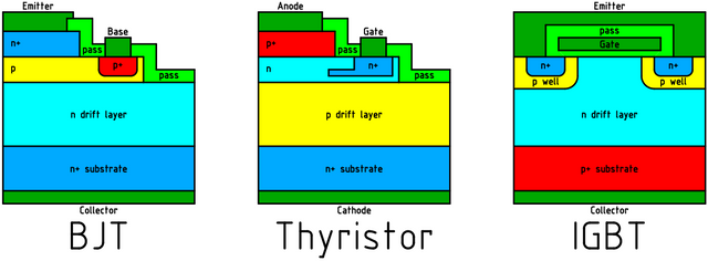
Problems related to the current source converter (CSC) is that it require a bipolar switches for its operation, although commercial version of bipolar switches available like GTO, IGCT but it operates at low frequency. In this case VSCs using IGBTs a fully controlled switch provides a greater flexibility in controlling the real and reactive power independently and hence the solution to stability and power exchange related issue.
Now a day’s power system based on AC transmission works at high risk as it operates at bode neck of stability margins. Even a small disturbance can challenge transient stability and restore itself within a certain time it leads to.
Hence as a solution to the above problem VSC-HVDC voltage stability limits. If the system can collapse of complete power system with an efficient control strategy which is capable of controlling the active power and reactive power independently.
Objectives:
Objective of this design is a VSC-HVDC back to back converter and its control strategy to enhance the dynamic stability of power system. So that bulk power system can withstand to a wide variety of disturbance. It is desirable to design and operate so that most adverse possible contingencies do not result in an in an uncontrolled and cascaded power interruptions. In this VSC- HVDC back to back converter is used along with the parallel AC transmission line and its various control strategies to ensure a faster active and reactive power flow control, hence stability.
- 1.Performenge analysis in VSC- HVDC base transmission system.
2.modeling of VSC in SIMULINK environment.
3.focus on different control structure and its implementation for VSC controlling.
4.Analysis of system behavior for disturbance condition
Outline:
The control of VSC- HVDC and its application to the power system to enhance the system stability and efficient power exchange between two grids. This report is organized in six chapters.First chapter deals with the studied project, containing introduction, literature review, problem formulation, objectives.
Second chapter deals an overview of voltage source based HVDC transmission system, comparing HVAC and HVDC. Application and configuration of HVDC transmission system. Then comparison between CSC based HVDC and VSC based HVDC are discussed.
Third chapter represents the study related to stability issues of power system and enhancement using VSC-HVDC. Study of capability curve of VSC transmission.
Fourth chapter represents the design of control strategies for VSC- HVDC transmission system. PLL technique used to synchronize with the grid voltage. This chapter contains the design of current controller, DC voltage controller, real and reactive power controller and an AC voltage controller.
Summary:
This chapter provides the information about introduction to the topic HVDC, literature review and problem formulation. An overall objective to mitigate the problem.
