Welcome to the Steem Train. This is the first article ever. The purpose of the Steem Train...To educate individuals.
I am going to start out the Train with an introduction to Ladder Logic. Or more commonly called machine code. So without further ado:
Steam Train Article #1 Introduction To Ladder Logic.
Ladder logic was originally a way to write out a control circuit for a rack of relays. Before the time of the PLC(Programmable Logic Controller), industries controlled their process machinery by turning relays on and off with use of operator interfaces or timer / trip type circuitry. These relays drove the coils which controlled the machinery for the process which needed to be completed.
To understand Ladder Logic, one must first understand the relay. A relay is just as it sounds, it is a component which transfers electrical current from one point to another when it is energized. A single relay consists of usually 5 connection points. An 'A1' an 'A2' a '11' a '12' and a '14'. A1 and A2 are your coil connections. The coil is what drives the relay to switch between contacts. When it is energized, the normally open(N.O.) contacts close and the normally closed(N.C.) contacts are opened. Normally open means in the components non-energized state the contact is not connected to the relays pole. (The pole is the connection that is transferred from contact to contact) Normally closed means just the opposite, the contact is connected to the relay pole while the relay is non-energized. Now with that being said, a normally open contact can be visualized as two wires not connected together, or as the symbol -| |- and is called the XIC(Examine If Closed). , a normally closed contact can be visualized as a two wires which are connected together, or as the symbol -| / |- and is called the XIO(Examine If Open). A coil is represented by the symbol -( )- and is called the OTE(Output Energize). It can be said that the coil of the relay is the controlling factor of the contacts. As it depends on the coils state which contact the current will flow.
On the relay I am discussing there are three control connections. 11, 12 and 14. Connection 11 is the pole, connection 12 is normally closed and connection 14 is the normally open. If I were to draw this out it would look a bit like this:
If I were to label the N.O. symbol to the connections of the relay it would appear like this:
-------11-[ ]-14-------
If I were to label the N.C. symbol to the connections of the relay it would appear like this:
-------11-[ / ]-12-------
If I were to label the coil symbol to the connections of the relay it would appear like this:
-------A1-( )-A2-------
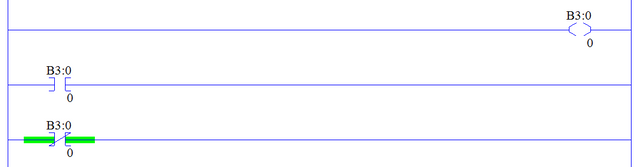
For right now we will not concern ourselves with the naming labels you see...B3:0/0...We will talk about these in a future Steam Train article. The lines on the left and right represents current or power flow. The object is to get the power from the left side line to the right side line.
Knowing that the OTE represents the coil of our relay it can be said that when the OTE has power flow to it that we should have some change to the N.O. and N.C. contacts associated to the OTE. In fact the symbols work exactly like the relay does. When the OTE has power flow, the associated N.O. contact allows power to pass and flow through it, as well as the associated N.C. contact opens and blocks power flow from passing through it.
By utilizing this format, you can begin to write simple control logic, if this OTE then this; if not this OTE then this. Your logic code begins to form multiple coils driving contacts which in-turn drive more coils finally culminating to some real world output interaction.
The XIC, XIO, and OTE are the most basic Ladder Logic instructions you can use. Having a good understanding of how they work will help you extremely when it comes to controlling power flow throughout your Ladder code. These are the If...Then... operators when it comes to machine control.
In the next article we will discuss some compare instructions. Compare instructions consist of the GEQ, GRT, EQU, LES, and LEQ to name a few. (Greater Than Or Equal To, Greater Than, Equal, Less Than, Less Than Or Equal To)
Until next time, keep it on the rails!
Cash