The Sea Axe: CAD Modelling

As this project & subject is somewhat introductory, we are mainly concerned with modelling (no analysis) and therefore have had a look at a few applications namely; Maxsurf [by Bentley], Rhinoceros [Rhino3D] and AutoCAD [Autodesk], for the modelling of the vessel. We used mainly Maxsurf and AutoCAD because we were finished well ahead of the others, so we really only used Rhino as a familiarisation exercise.
Maxsurf

Maxsurf is a Non Uniform Rational B-Spline NURBS modeller, that is specific to the ship building industry. MAXSURF includes tools for hull modelling, stability, motions and resistance prediction, structural modelling, structural analysis, and export to vessel detailing.
There are many useful tools for producing fair and accurate surfaces and evaluating curvature. Fairing in the real world is the act of filling and shaping sruface so the blend smoothly with surrounding surfaces and therefore appear "fair". It is the similar in Maxsurf to ensure when you export the frame, you have a suitable number of frames to correctly represent the curvature that you are trying to achieve.
The Following is a screen shot of our model, showing the modelling environment of Maxsurf. The Green lines you see in the perspective view correspnond with the station numbers along the hull. A section of the hull will be created at these stations and exported to create the frame work of the vessel model.

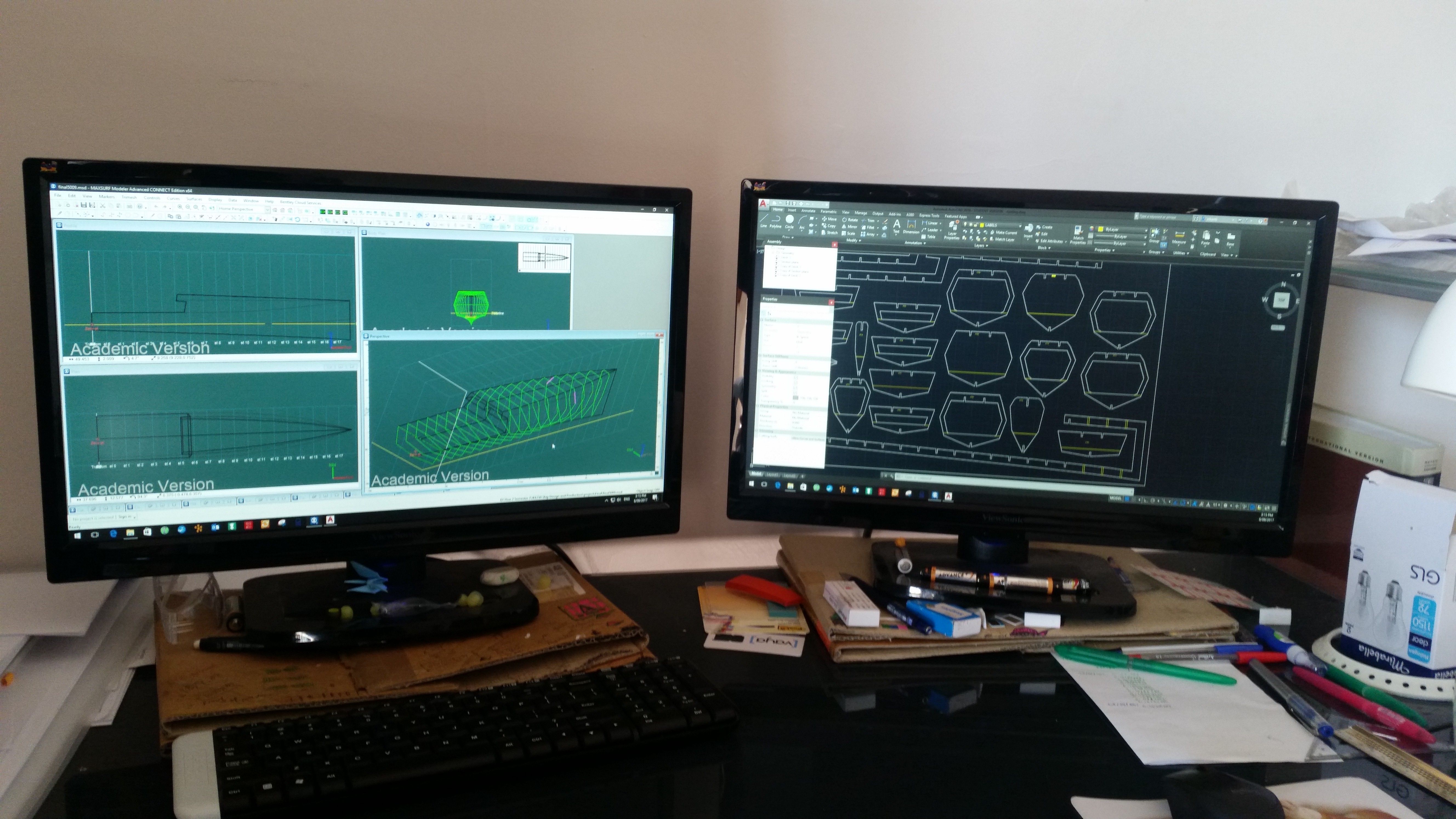
AutoCAD was used to process the frames and arrange the sheet for laser cutting. I have worked extensively with AutoCAD in the past so this process didn't take much effort at all. In the photo below you can see Maxsurf on the left screens and AutoCAD on the right after the frames have been exported and arranged on the sheet. The line work on in AUtocad also has to be arranged on the correct layers so the laser cutter knows what to cut and what to "score". For instance the "designed waterline" is a score mark, and does not need to be cut all the way through, also there were some text and numbering that were scored into the card board.

The frames are exported on top of each other (purple lines) as shown below, however they have been placed on a separate layer each, i.e. ST0, ST1... ...ST17 etc

The frames are then arranged on to a cutting sheet, ready for submission.

Different Views OF The Model


Next Post: Cutting and Frame Construction
The following post will be about the development of the CAD Model and preparation of the parts sheet for laser cutting. If you are interested come back and check on our progress through the post project.
Previous Posts:
Part 1: Part-1-Introducing-The-Sea-Axe-5009
https://steemit.com/technology/@rezantroy/part-1-introducing-the-sea-axe-5009My Current Quotes
I have never understood why it is "greed" to want to keep the money you have earned but not greed to want to take somebody else's money.
Thomas Sowell
I chose this quote as I like Thomas Sowell and I have been thinking lately on the fairness of how the proceeds of our labour are spent, he also said:
Helping those who have been struck by unforeseeable misfortunes is fundamentally different from making dependency a way of life.
Thomas Sowell
Thanks for stopping by and having a read

