What is Snapshot Positioning? (Part 3 – Data Buffering and Data Storage Modules)
In the previous blog posts in this series, I explained #SnapshotReceiver and one of its discrete modules – Data Capture.
To jog your memory, you can find Part-I and Part-II here.
One advantage of snapshot receiver is that once the #GPS satellite signal has been captured, it does not need to be processed right away. This means that the parts which consume the most energy can be offloaded to a remote device that has a much greater processing capacity, speed and efficiency. In this blog post, we will be discussing why and how Data Buffering and Data Storage may be required in a design.
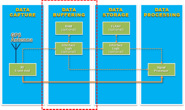
Data Buffering Module

The MAX2769 #RFIC has a very flexible architecture in which it can be configured to output different IF data formats between 1 MSPS and 16 MSPS (mega-sample per second). For an optimized #UltraLowPowerGPS receiver design, we found out that the best configuration is by using 2-bit I, 2-bit Q at 4.092 MSPS – this means the RFIC will split the IF data into 4 separate data lines – I0, I1, Q0 and Q1 and output them at a fairly high data rate of 4.092 MSPS per data line.
Although I mentioned in my previous blog posts that snapshot receiver requires only a few milliseconds of IF data to obtain a position and the data size is only a few kilobytes per capture, however the speed at which the RFIC outputs the IF data (data rate) could be too high for some low-cost MCUs to read. In this case, a Data Buffering module may be needed to temporarily store the data before sending it to the Data Storage or Data Processing Modules.
There are many ways to implement the interface logic of the Data Buffering module. One simple way is to connect each data line to an 8-bit serial to parallel SIPO shift register chip such as the 74164 series to slow down the incoming 4.092 MSPS data stream to 0.5115 MSPS.
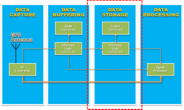
Data Storage Module

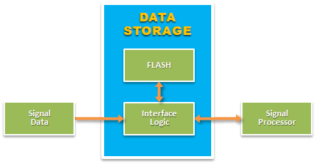
Similar to the Data Buffering module, depending on how the RFIC interfaces with the MCU – Microcontroller, the Data Storage module is optional.

For #Wearables and #IoT applications such as fitness watches that must continuously track a user’s position while operating on a small battery, minimizing power consumption is paramount. One strategy is to force the snapshot receiver to remain in a state of deep sleep most of the time. The snapshot receiver will only wake up to periodically capture a user’s position by turning ON the RFIC for a few milliseconds and store the captured signal data to non-volatile memory e.g. flash memory or SD card etc. As soon as the capture is completed, the snapshot receiver will immediately go back to a ‘deep sleep’ state to conserve power.
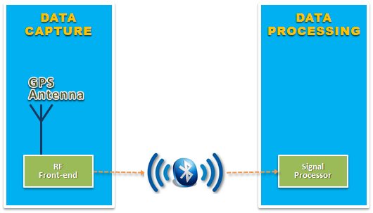
Another unique advantage of snapshot receiver is that once the captured signal data is stored in non-volatile memory, it can be retrieved for processing at any time in the future which can be done on the device itself, a cloud server or even a computing device near the snapshot receiver. For example, a low power Bluetooth-enabled wristband can be programmed to continuously capture and store the IF data until it is connected to an external power source e.g. while recharging, where the captured data can be conveniently sent to a remote server or to a nearby smartphone for signal processing.

In this blog post, we have discussed why and how the Data Buffering and the Data Storage modules might be necessary for a snapshot receiver. By now, you have probably already noticed that there are rigid requirements for users to connect conventional receivers to their hardware environment. In contrast, state of the art snapshot receiver provides an extremely flexible architecture for users to integrate it to their hardware environment to achieve maximum energy efficiency.
In the next blog post, which hopefully would mark the end of this “What is Snapshot Positioning” mini-series, I will discuss the Signal Processing module in more detail. I hope to see you then!