PART 2
Starting 1/4-in. from the end, begin winding clockwise, making all
turns as tight and as close together as possible. Avoid kinks and
overlapping.
Total number of turns will be about 3350, but there is no need
to keep count since the turns are closely spaced. Leave about two
feet
of wire free at the end. Stop winding 1/4 in. from the opposite end
of the tube and run a 3-in. length of the wire through a small hole
Drilled in the exposed cardboard apparatus.
This end will be the top of the secondary. Apply several coats of
varnish to the windings for protection and insulation.
To make the discharge electrode, fit the top of the secondary with
a porcelain, center-fed insulator of any type (length should not exceed
3 in.). Insert a bolt through the center of the insulator and attach the
3-in. coil wire to the bottom end of the bolt. No more than 3/4 in. of
the bolt should protrude from the insulator top. Fasten the insulator
to the end of the secondary coil with electrical tape or other.
Make a wood base for L2 by cutting a 10" square from 3/4 "
plywood, and fastening a 6-in. long wooden dowel to the center. Use
a 3-in. wood screw to attach the dowel, and, or glue it in place. The
secondary should fit snugly over the dowel.
The 2-ft. length of coil wire from L2 can be brought through a
1/4-in. hole drilled in the platform 1 in. from the dowel. another
option for the base L2 would be to use 1/2" to 3/4" clear plastic.
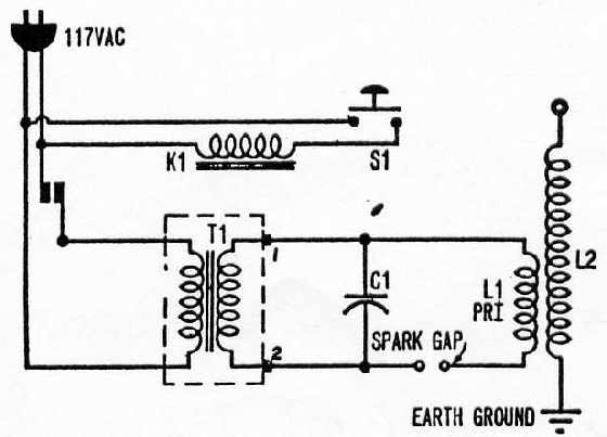
Primary coil LI. which fits at the base of the secondary, consists
of 28 closely-spaced turns of AWG 8 insulated copper wire on a 10
x 5 1/4 in. Quaker Oats box. or use a 4" PVC pipe. In a pinch,
ordinary two-conductor line cord can be used, with the ends twisted
together to form one conductor. The box should be varnished and it
can be reinforced with a few layers of fiberglass cloth and epoxy resin.
To wind LI, secure the first turn at the bottom of the box with
a piece of string, then wind clockwise until 28 turns have been made.
Do not wind the entire length of the box, but keep the turns as closely
spaced as possible. Secure the last winding with electrical tape.
Cut a hole in the bottom of the box and slip the completed LI over
L2, keeping the secondary centered. The exposed cardboard of the
Parts List for Tesla Lightning Generator. Table 1-2.
- SI-S.p.s.t. pushbutton switch , 2. T1-15,000-volt, 30-mA. neon-sign transformer
- 1-Spark gap (see text). 4. 1-16 x 20 x 5-in. deep box (plastic or wood-see text)
- 1-porcelain insulator for discharge terminal. 6. 1-36 1/2x1 7/8-in. OD tube (cardboard,
phenolic, or other non-conductor) - 1-10 x 5 1/4-in. OD tube (cardboard, phenolic, or other non-conductor-see text)
- K1-5-amp. contact, 120-volt coil relay (Potter & Brumfield type MR3A or equiv.)
- L1-38-feet AWG-8 solid insulated wire wound on 5 1/4-in. form.
- 1-2-1650 feet AWG-30 enameled solid copper magnet wire (approximately a 1/2-lb.
spool) wound on 1 7/8-in. form. - 3-SAE-30 motor oil, quart cans
- 8-12 1/4 x 16 1/2 x 1/4-in. sheets of glass (to fit box above-see text)
solder, insulating varnish or epoxy, tape, etc.
primary can be painted with nonconducting enamel or wound with
tape.
The Low-Leakage Capacitor
You can build a larger capacitor such as our homemade capacitor
designs ( see # HVC1 plans ) or you can build the following.
You will need a box about 16 x 20 x 5 in. for capacitor Cl. A
box can be made of 1/4- or 1/2-in. plywood and reinforced with
fiberglass. Box size is not critical, though the box must be large enough
to hold the capacitor about to be described.
Glass dielectric for the capacitor consists of eight sheets of 16 1/2
x 12 1/4 x 1/4-in. window glass. Cost should run about $30.
Cut out seven sheets of 20- x 9-in. heavy-duty aluminum foil and
assemble Cl as follows: lay a sheet of glass in the box and place a
sheet of 20- x 9-in. aluminum foil on the glass as shown in the
drawings. Pour in just enough ASA 30 motor oil to cover the foil. On
top of this lay another sheet of glass and aluminum foil, but be sure
to reverse the tab or free end of foil to that it protrudes from the
opposite side of the glass.
Press all air bubbles from between the glass. This done, pour in
more oil and continue the process, always alternating each sheet of
foil. Bend the foil tabs together on each side of the capacitor in order
that wires from the rest of the circuit can be connected to them. About
three quarts of oil will be needed for a 16- x 20-in. box. Wooden blocks
can be wedged around the plates as a means of keeping them from
shifting .
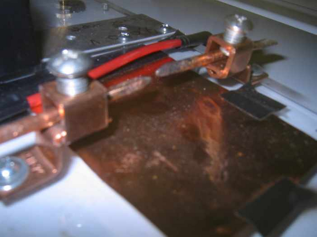
There are a num ber of ways to m ake the spark gap , but the best
arrangement consists of two 1/2-in. diameter conductors adjustable
from 1/4- to 1-in. separation. or try a spark plug.
A simple gap can be made by mounting two 1/2-in. diameter bolts
through nuts brazed on 1- x 2-in. metal plates. The plates are mounted
on a varnished wood block at least 1 3/4-in. thick to prevent arcing
around the gap (see our illustrations).
Power for the circuit is supplied by a 15,000-volt, 30 mA neon -
sign transformer. New transformers cost about $120 or more-used
ones are considerably less.
Wire the circuit with AWG 12 or 14 single-conductor copper wire,
as it is stiff enough to be self-supporting. Route all wires separate from
each other and other objects, keeping in mind that high voltages will
be present throughout most of the circuit. Capacitor Cl is wired into
the circu it by atta ching wires directly to the a lumin um f oil tabs. P lace
components according to drawings.
Operating the Generator
When the circuit is ready for testing, connect the ground wire from
the bottom of the secondary to a water pipe or telephone ground.
Tuning
If the spark-gap is operating, but either a weak discharge or none
at all appears at the top of L2, the coil will have to be tuned. This
is accomplished by varying the number or size of the aluminum foil
sheets in Cl and by varying the effective turns on LI.
It's easier to begin tuning by varying the exposed area of the top
sheet of aluminum foil and by "tapping in" a few turns down from
the top of the primary. Maximum discharge generally will be reached
with a total variation of no more than two or three turns on coil LI
and one full sheet of aluminum foil in Cl.
If reducing the number of turns in LI and changing the number
of plates in Cl doesn't help, try adding several turns to LI by splicing
in additional wire. An additional sheet of foil can be added to the ca-
pacitor, but another sheet of glass will be needed also.
It is best not to operate the Generator for more than 15 to 20
seconds continuously without an equal time off, as the oil in the ca-
pacitor will start to break down, allowing arcing to occur. But if you
build our home made HV capacitors or use an old microwave AC
or DC capacitor you will get better results.
Remember to be careful. High voltage can kill and is much more
powerful after it enters a large capacitor, wear rubber gloves.
Spark Gap using 2 large copper wires and Electrical box fasteners
You can also use a spark plug or make your own out of wood and
2 separate metals, attach one on top of wood block and one on bottom.
Drill 2 holes in each of the metal pieces and place nuts and bolts in them
so they can adjust. These are your electrodes.