Introduction
This is a tutorial of an open source Arduino library, which lets you turn your Arduino to a “Color Scanner”, with a TCS3200 RGB color sensor module, that scans any objects color and converts it to RGB values. I will show you how to install the library to Arduino IDE and make an example project with the library, throughout this tutorial while giving information color sensors and their working principle.
What Will I Learn?
In this tutorial you will learn:
- General knowledge about color sensors.
- How to install MD TCS230 RGB color sensor library to Arduino IDE.
- How to use MD TCS230 library and how to use Its functions.
- How to apply color scanner project using the library functions.
Requirements
This tutorials requirements are:
- Arduino UNO or equivalent microprocessor.
- Arduino IDE (Download here)
- MD TCS230 RGB color sensor Arduino library (Download here)
- TCS230 RGB color sensor module, Breadboard, Jumper wires, black and white color objects for calibration.
Difficulty
This tutorials difficulty is:
- Intermediate
Tutorial Contents
What is a Color Sensor and How It Works
Color sensors (In other words RGB sensors) are essentially light sensors. They shine a white light to an object, then they perceive and record the reflected color. Since they are light sensors, they can measure brightness. Color sensors are often called RGB sensors because there are three main colors of light: Red, green and blue. These three lights have different wavelengths, red light has approximately 680 nm wavelength, blue light has 450 nm wavelength, and green light has 520 nm wavelength. Since all these lights have different wavelengths, they can be districted within their wavelengths, even with some calculations they can be mapped into R, G and B values from 0 to 255. Color sensors are used for mainly two purposes: true color recognition and color mark detection.

Color sensors “sense” three colors in the spectrum – red, green and blue. Image Source (CC0))
How to Install TCS230 RGB Color Sensor Library to Arduino IDE
1. Download the library from https://github.com/MajicDesigns/MD_TCS230.
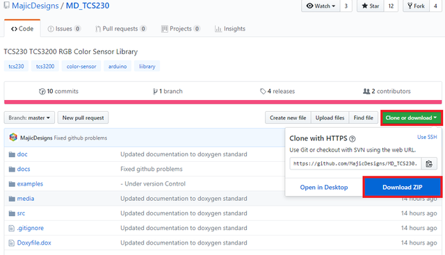
2. Open Arduino IDE. Then go to and select Sketch->Include Library->Add .ZIP Library.
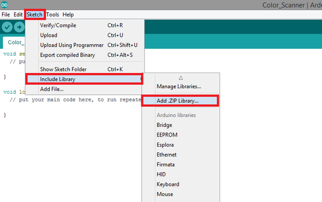
3. Choose MD_TCS230-master.zip file and click to Open.
An Example Project Using TCS230 RGB Color Sensor Arduino Library
I'll show you step by step how to use the TCS230 RGB Color Sensor Arduino library with a simple example. In this example project, we will make a “color scanner” with a Arduino microcontroller and a TCS230 RGB color sensor module which senses colors and prints their RGB values to serial monitor. See the steps for how to do these actions. Connections for TCS230 RGB Color Sensor module to Arduino is shown below.
If you use this library in your other projects please tell in the comments.
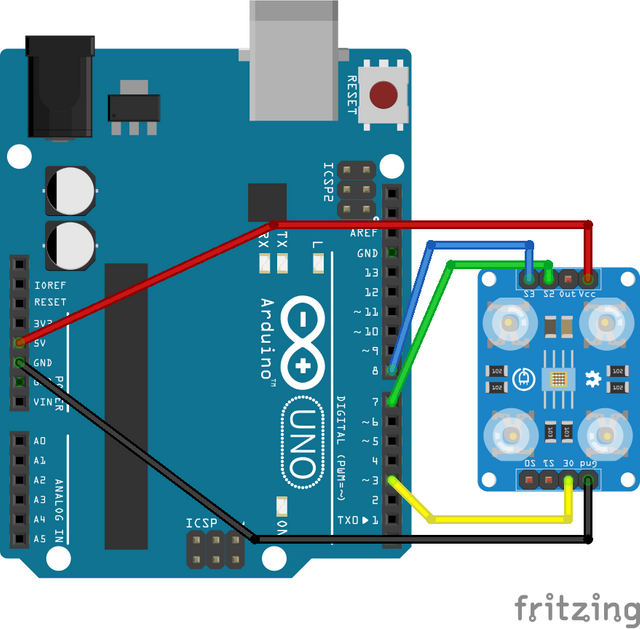
Connection diagram for TCS230 RGB Color Sensor module to Arduino. Made with Fritzing.
1. Open a new sketch and save it as "Color_Scanner”.
2. To add our libraries to our sketch, type #include <MD_TCS230.h> and #include <Wire.h> at the beginning of the code.
3. After adding the libraries, define the pins we’ll use for module connection. Make sure you select digital pin 3 for OE output, digital pins 7 and 8 for S2 and S3 outputs respectively.

4. Create the TCS230 library instance. Then define a 256 value byte array that we'll use for storing and displaying RGB values. Define red, green and blue integer values for printing.

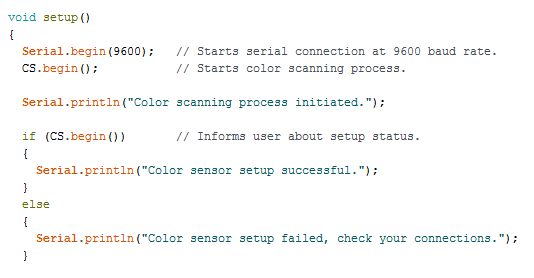
5. In the void setup() function write the command that starts serial connection at 9600 baud rate. Initiate color scanning process by adding the library function. Then add the user information about setup process by creating an if-else condition; if statement will trigger when color scanning process is initiated, that will print that the connection and setup is successful. In the else part inform the user that there is possibly a error with the connection, therefore setup could not be done.
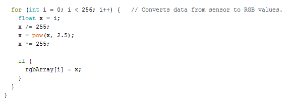
6. Create a for loop for converting signal data from frequency to RGB hex values. Add the codes below if you can’t figure out the conversion equation.
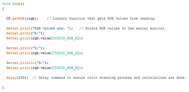
7. In the void loop() function, add the library function that gets RGB values from reading. Then add the print commands that will print red, green and blue values of the scanned objects respectively to the serial monitor. Add a 100 ms delay command to ensure color scanning process and calculations are done.
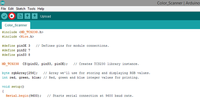
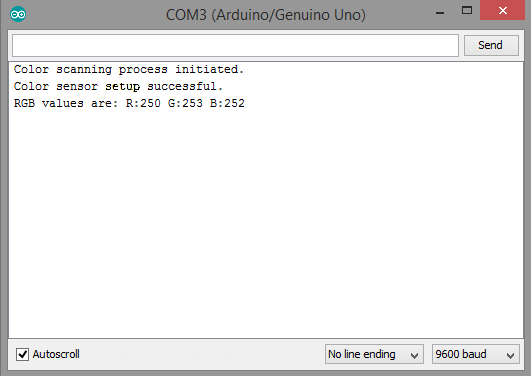
8. Click “Verify” and then “Upload” in order to compile and execute your codes. You should see a readings screen like this. Make sure your COM port and board setting is set right. Please double check the ground connections and all your wirings before running the code.
Conclusion
In this tutorial I’ve shown how to install “TCS230 RGB Color Sensor” Arduino library, written by GitHub user “MajicDesigns” to Arduino IDE, showing how to use the library functions with an example, while giving information about color sensors.
I hope that you enjoyed this tutorial and the information that I’ve given. Thank you for reading.
If you want more information about the library and the source use the link below.
Github: https://github.com/MajicDesigns/MD_TCS230
Code
#include <MD_TCS230.h>
#include <Wire.h>

#define pinOE 3   // Defines pins for module connections.
#define pinS2 7
#define pinS3 8

MD_TCS230  CS(pinS2, pinS3, pinOE);   // Creates TCS230 library instance.

byte rgbArray[256];   // Array we'll use for storing and displaying RGB values.
int red, green, blue; // Red, green and blue integer values for printing.

void setup()
{
  Serial.begin(9600);   // Starts serial connection at 9600 baud rate.
  CS.begin();           // Starts color scanning process.

  Serial.println("Color scanning process initiated.");

  if (CS.begin())       // Informs user about setup status.
  {
    Serial.println("Color sensor setup successful.");
  }
  else
  {
    Serial.println("Color sensor setup failed, check your connections.");
  }


  for (int i = 0; i < 256; i++) {   // Converts data from sensor to RGB values.
    float x = i;
    x /= 255;
    x = pow(x, 2.5);
    x *= 255;

    if {
      rgbArray[i] = x;
    }
  }
}


void loop()
{

  CS.getRGB(&rgb);    // Library function that gets RGB values from reading.

  Serial.print("RGB values are: ");   // Prints RGB values to the serial monitor.
  Serial.print("R:");
  Serial.print(rgb.value[TCS230_RGB_R]);

  Serial.print("G:");
  Serial.print(rgb.value[TCS230_RGB_G]);

  Serial.println("B:");
  Serial.print(rgb.value[TCS230_RGB_B]);

  delay(100);  // Delay command to ensure color scanning process and calculations are done.

}
Previous Tutorials
- MFRC522 RFID Reader Arduino Library Setup and Functions Usage Shown With an Example Project - Tutorial
- MPU6050 3 Axis Gyroscope & Accelerometer Module Setup, Arduino Library Use Shown With an Example Project
- Adafruit PCA9685 PWM Servo Driver Setup, Arduino Library Use Shown With an Example Project
- Making a Telegram Chat Bot With the TelegramBot Arduino Library and ESP8266 Wifi Module
Posted on Utopian.io - Rewarding Open Source Contributors
Thank you for the contribution. It has been approved.
You can contact us on Discord.
[utopian-moderator]
Downvoting a post can decrease pending rewards and make it less visible. Common reasons:
Submit
Hey @forkonti, I just gave you a tip for your hard work on moderation. Upvote this comment to support the utopian moderators and increase your future rewards!
Downvoting a post can decrease pending rewards and make it less visible. Common reasons:
Submit
@drencolha, Upvote for supporting you.
Downvoting a post can decrease pending rewards and make it less visible. Common reasons:
Submit
Hey @drencolha I am @utopian-io. I have just upvoted you!
Achievements
Suggestions
Get Noticed!
Community-Driven Witness!
I am the first and only Steem Community-Driven Witness. Participate on Discord. Lets GROW TOGETHER!
Up-vote this comment to grow my power and help Open Source contributions like this one. Want to chat? Join me on Discord https://discord.gg/Pc8HG9x
Downvoting a post can decrease pending rewards and make it less visible. Common reasons:
Submit