What Will I Learn?
In this tutorial, readers :
- will learn the basics of JK flip-flops
- will learn basics of counters
- will be able to construct 4-bit counter on SimulIDE

Requirements
In order to complete the tutorial, reader would have:
- basic idea about digital circuit design
- basic idea about logic gates
- basic knowledge on SimulIDE
Difficulty
- Intermediate
Tutorial Contents
In this tutorial, I am going to construct 4-bit Synchronous UP counter on SimulIDE. I will start my tutorial with explaining JK Flip-Flops, and the basic operation principle of counters, (especially for sycnhronous up ones) and then basically explain how to construct the circuit on the software, and as a last part I am going to show the results of the circuit that I have construct for this tutorial.
BEFORE GOING INTO FURTHER IN THIS TUTORIAL I HIGHLY RECOMMEND THAT READER SHOULD DIGEST MY PREVIOUS TUTORIAL WHICH SHOWS THE LOGIC GATES AND CIRCUIT CONSTRUCTION IN THE SOFTWARE
- Episode 1: What is JK Flip-Flop?
Before explaning JK Flip-Flop, let me give a description of flip-flops in general.
Flip-flops, also called bistable gates, are digital logic circuits that can be in one of two states. Flip-flops maintain their state indefinitely until an input pulse called a trigger is received. When a trigger is received, the flip-flop outputs change state according to defined rules and remain in those states until another trigger is received.
There are several different kinds of flip-flop circuits, with designators such as T (toggle), S-R (set/reset) J-K and D (delay). A flip-flop typically includes zero, one, or two input signals as well as a clock signal and an output signal. Some flip-flops also include a clear input signal to reset the current output.
In this tutorial, we are mainly focused on JK flip flops, so I will explain it in detail.
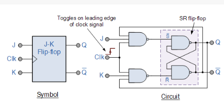
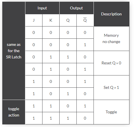
JK flip flop is modified version of SR(set-reset) flip flop with a feedback mechanism that makes either SET or RESET to be active at a time, gives better solution compared to SR flip flop. The table below shows the truth table of JK flip flops:
- Episode 2: What is 4-bit Synchronous UP counter and how to construct it?
(Note that those topics may be hard to digest at the first stage, so I highly recommend that reader should follow the links that I used for the sources.[I will link them at the end of the tutorial])
2.1 What is counter?
Counter is a digital device and the output of the counter includes a predefined state based on the clock pulse applications. The output of the counter can be used to count the number of pulses.
2.2 What is synchronous counter?
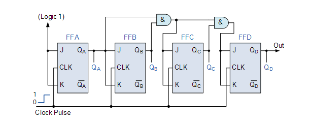
In synchronous counters, the external clock signal is connected to the clock input of EVERY individual flip-flop within the counter so that all of the flip-flops are clocked together simultaneously (in parallel) at the same time giving a fixed time relationship. In other words, changes in the output occur in “synchronisation” with the clock signal.
4-bit Synchronous Up counter that I am going to construct is given below:
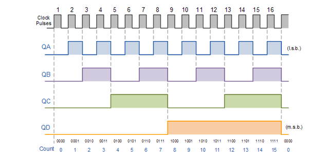
And the expected result should look like:
- Episode 3: Construction of 4-bit Synchronous UP counter circuit in SimulIDE
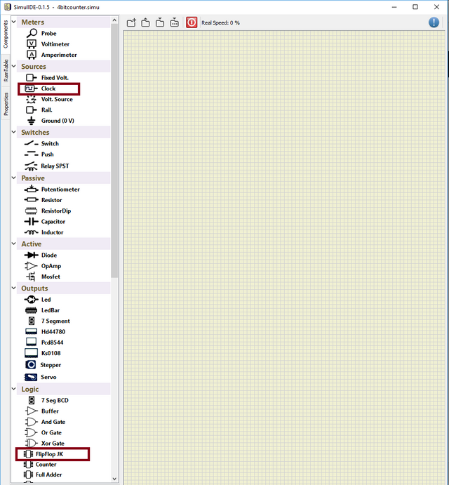
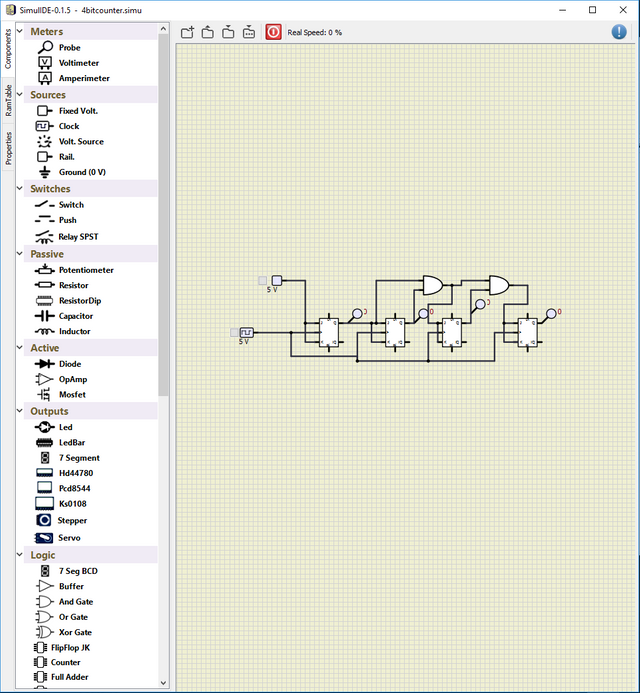
Construction is a bit easier than the theory that I have provided above. Reader should be capable of construct the circuit almost completely after understanding my previous tutorials (here and here). Reader will need extra 2 components, which are Clock and JK Flip Flop on Components Table.
Constructed circuit should look like:
We are able to adjust the frequency of clock by right click ---> properties
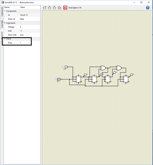
Note that I have set the frequency as 1. And also I let the preset and reset inputs of JK Flips Flops as open circuit since we do not need them. So we are ready to simulation.
- Episode 4: Simulation of 4-bit Synchronous UP counter circuit in SimulIDE
All we need to do is just click simulation button provided below:
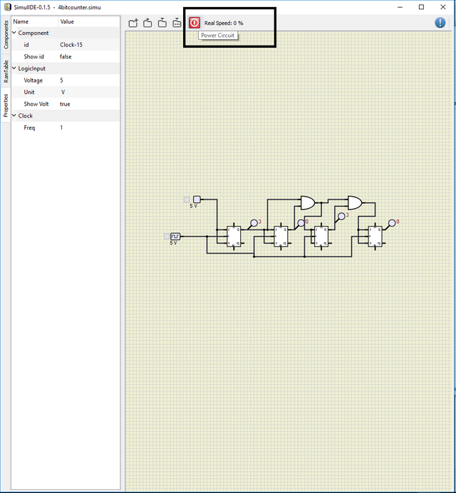
Result of the simulation is:
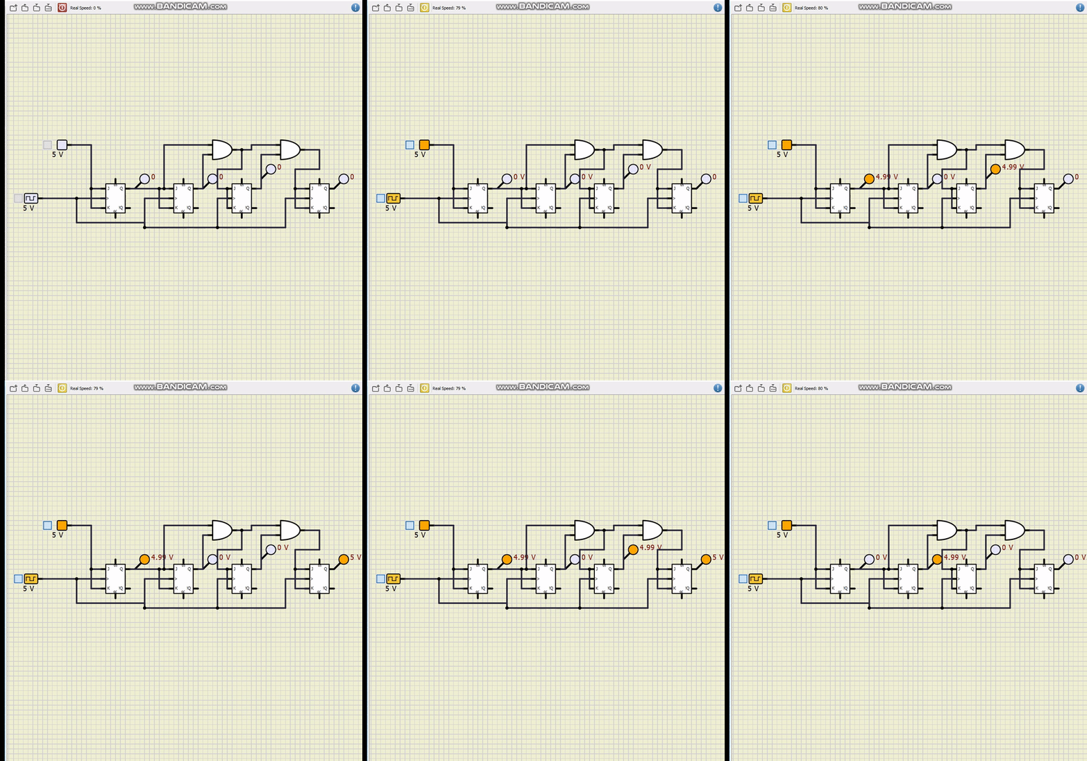
If we look at the simulation results & expected results, we can say that they are identical, so we have managed to construct our circuit.!
I have provided the files for this tutorial here. I highly recommend that the reader should work on the files that I have provided and try to understand the basics of the circuit & software. It will be benefical for he/she.
This is the end for this tutorial.Hope that you like it.
SimulIDE is a really effective and easy to learn software, I highly recomment this software for the one who wants to make simulation in digital circuits especially.. If you have any questions, please feel free to ask me on Discord (Escorn#4114)
Sources
Source for the JK Flip Flop figure & truth table
Source for the synchronization quote
Source for the circuit that I have constructed & result graph
Curriculum
I have provided the previous tutorials that I have prepared for the community:
| SimulIDE | Caneda |
|---|---|
| Part 1 | Part 1 |
| Part 2 | Part 2 |
| Part 3 | Part 3 |
| Part 4 | Part 4 |
| - | Part 5 |
| - | Part 6 |
| - | Part 7 |
| - | Part 8 |
| - | Part 9 |
Posted on Utopian.io - Rewarding Open Source Contributors
Your contribution cannot be approved because it does not follow the Utopian Rules.
Gathering pictures, text point from different websites is not accepted
You can contact us on Discord.
[utopian-moderator]
Downvoting a post can decrease pending rewards and make it less visible. Common reasons:
Submit